




 Nederlands
  Suomi
Suomi  Ελληνικά
  Български
  Hrvatski
  Frans
Frans  Deutsch
  Italiano
  Español
  Polski
  Dansk
Dansk  Čeština
  Svenska
  Aileen
Christmas tree solder kit (OT2647 SH series) – instruction manual
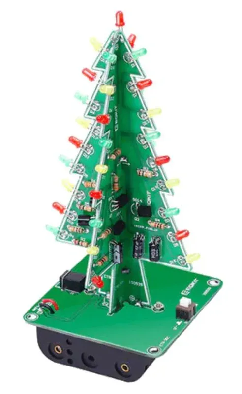
This instruction manual shows you how to assemble the OT2647 SH series Christmas tree solder kit, a small Christmas tree with flashing red, green, and yellow LEDs. Required tools: soldering iron, solder, and wire cutters.
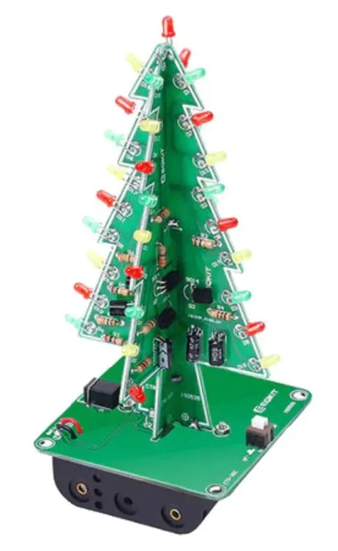
Parts list
| Component | Location | PCB code | Quantity |
|---|---|---|---|
| Resistor 100 Ω | R2/R4/R6/R7 | SH-A | 4 |
| Resistor 4.7K Ω | R1/R3/R5 | SH-A | 3 |
| Capacitor 47 µF | C1/C2/C3 | SH-A | 3 |
| LED 3mm red | D1 t/m D6 + D19 | SH-A | 7 |
| LED 3mm yellow | D7 t/m D12 | SH-A | 6 |
| LED 3mm green | D13 t/m D18 | SH-A | 6 |
| Transistor 9014 | Q1 t/m Q3 | SH-A | 3 |
| Resistor 100 Ω | R2/R4/R6 | SH-B | 1 |
| Resistor 4.7K Ω | R1/R3/R5 | SH-B | 1 |
| Capacitor 47 µF | C1/C2/C3 | SH-B | 3 |
| LED 3mm red | D7 t/m D12 | SH-B | 6 |
| LED 3mm yellow | D13 t/m D18 | SH-B | 6 |
| LED 3mm green | D1 t/m D6 | SH-B | 6 |
| Transistor 9014 | Q1 t/m Q3 | SH-B | 3 |
| Switch 5.8mm | S1 | SH-C | 1 |
| DC socket 3.5mm | J1 | SH-C | 1 |
| Battery holder 3xAA | BAT4.5V | SH-C | 1 |
Package contents
- 1x PCB SH-A
- 1x PCB SH-B
- 1x PCB SH-C
- 7x Resistor 100 Ω
- 6x Resistor 4.7K Ω
- 6x NPN Transistor S9014
- 6x Capacitor 47µF 16V
- 13x LED 3mm Red
- 12x LED 3mm Green
- 12x LED 3mm Yellow
- 1x USB to DC 3.5mm cable
- 1x DC socket J1 3.5mm
- 1x Switch S1 5.8mm
- 1x Battery holder for 3x AA batteries
- 1x Otronic Dutch instruction manual
Resistors


The PCBs have a unique code. In the overview on the back of this instruction manual, it is indicated for each PCB which components you need to solder. For example: R6 on PCB CTR-30A is a different resistor than R6 on PCB CTR-30B. The LEDs are arranged in a specific order in this manual, but may also be placed in a different order if desired.
Assembly instructions
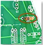 Start by soldering the resistors. Resistors are not polarized, which means they can be placed in either direction and there is no + or –.
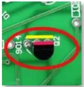 Solder the transistors and make sure that the flat and round sides match the illustration on the PCB.
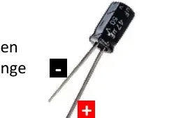
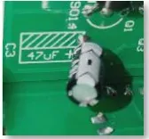 Solder the capacitors and pay close attention to the + and the -. The capacitor has a white band shown with a minus sign inside it. You can also tell by the length of the leads. The long lead is the + and the short lead is the -. On the PCB, the slanted white stripes indicate the - side.
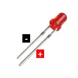
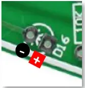 Solder the LEDs according to the diagram above. On the PCB there is a round and a square hole. The round one is the – and the square one is the +. On the LED, the long lead is the + and the short lead is the -. The minus side can also be identified by the flat side on the LED itself.
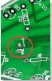 Once all components have been soldered, PCBs CTR-30A and CTR-30B can be slid together. Then solder the reinforcement points together so everything becomes a sturdy whole.
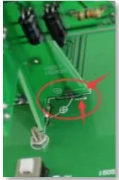 Now place the Christmas tree on the base plate CTR-30C and pay close attention to the + and the -. Then solder the tree in place. MERRY CHRISTMAS!
OTRONIC® is a registered trademark. Nothing from this instruction manual may be copied without permission from OTRONIC. For more information about OTRONIC products, visit OTRONIC.NL. OTRONIC – Crommelinbaan 61c – 2142 EX – Cruquius – Netherlands.