







 Nederlands
 Suomi
 Български
 Hrvatski
 Frans
 Deutsch
 Italiano
 Español
 Polski
 Dansk
 Ελληνικά
 Čeština
 Svenska
 Aileen
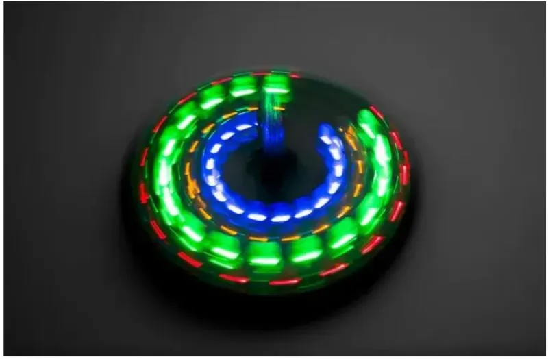
Light-Up Spinning Top with Motion Sensor (OT5817) – user manual
This user manual explains how to solder and build the OT5817 Light-Up Spinning Top with motion sensor yourself. You will need a soldering iron, solder and a pair of wire cutters for this.
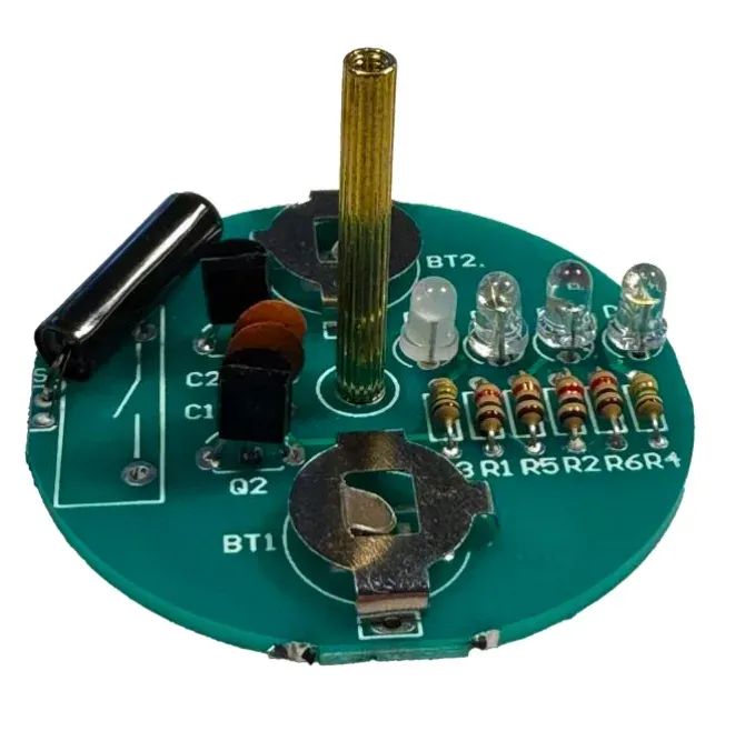
Parts list
| Component | Location | Quantity |
|---|---|---|
| Resistor 1K Ω | R1, R2, R5, R6 | 4 |
| Resistor 1M Ω | R3, R4 | 2 |
| Transistor S8050 | Q1, Q2 | 2 |
| Capacitor 0.1µF | C1, C2 | 2 |
| Vibration sensor | S1 | 1 |
| LED (various colors) | D1, D2, D3, D4 | 4 |
| Rod with screw | Center | 1 |
| CR1220 Battery | Battery holders | 2 |
| Transistor 9014 | Q1 t/m Q3 | 3 |
Package contents
- 1x Round circuit board
- 4x Resistor 1K Ohm
- 2x Resistor 1M Ohm
- 2x Transistor S8050
- 2x Ceramic Capacitor 0.1µF
- 4x 3mm LED various colors
- 2x Battery holder
- 1x Vibration sensor
- 1x Rotating shaft
- 1x Screw with nut
- 2x CR1220 3V coin cell battery
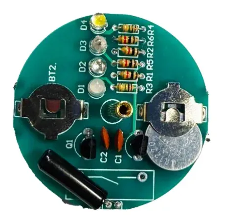
Circuit diagram
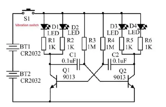
The components must be placed in the exact positions shown in the table on the back of this manual.
Also make sure you place the correct resistors in the correct positions. There are 2 types of resistors in this kit. The 1K Ohm resistor with the colors Brown, Black, Red, Gold and the 1M Ohm resistor with the colors Brown, Black, Green, Gold. Resistors are not polarized, so direction does not matter. There is no + or -.


Assembly
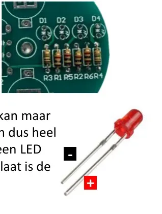 Solder all components onto the circuit board. Pay attention to the resistors, as they are different. The outer 2 are 1M Ohm (Brown/Black/Green) and the inner 4 are 1K Ohm (Brown/Black/Red). Direction does not matter.
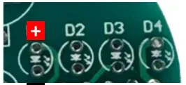 LEDs are diodes, so current can only flow in one direction. The + and – are therefore very important. You can identify the + side of an LED by the longer leg. On the circuit board, the + is the back of the arrow.
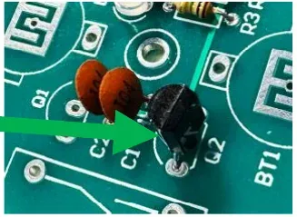 The black transistors are shaped like a half circle when viewed from above. Make sure you place them the same way in Q1 and Q2. The brown capacitors next to them on C1 and C2 can be fitted in either direction.
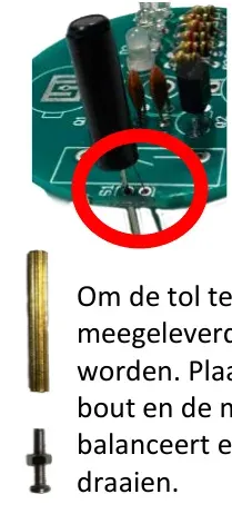 Do not place the vibration sensor right against the circuit board. After soldering, it must be bent so that it lies flat. Now only place the battery holders and your spinning top is technically complete.
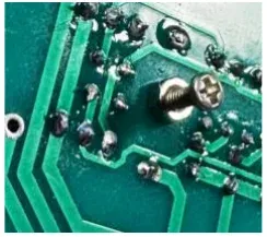 A gold-colored rod is included to make the top spin, into which the screw can be fitted. Place the circuit board between the rod and the screw and the nut. The screw is the point on which the top balances, and the gold-colored rod is used to turn it.
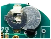 Insert the batteries (+ facing up = flat side) and the LEDs will light up when the top spins.
Enjoy!
OTRONIC® is a registered trademark. Nothing from this manual may be copied without permission from OTRONIC. For more information about OTRONIC products, visit OTRONIC.NL. OTRONIC – Crommelinbaan 61c – 2142 EX – Cruquius – Nederland.