Ordered on weekdays before 14:00 = shipped the same day and delivered the next day in 98% of cases. Free returns 30-day reflection period 1-year warranty

Wiring diagram and code example

How to connect the I2C-UART Bi-Directional Logic Level Converter 5V-3.3V 2-channel to an Arduino UNO or ESP32, with an example sketch you can upload straight away.

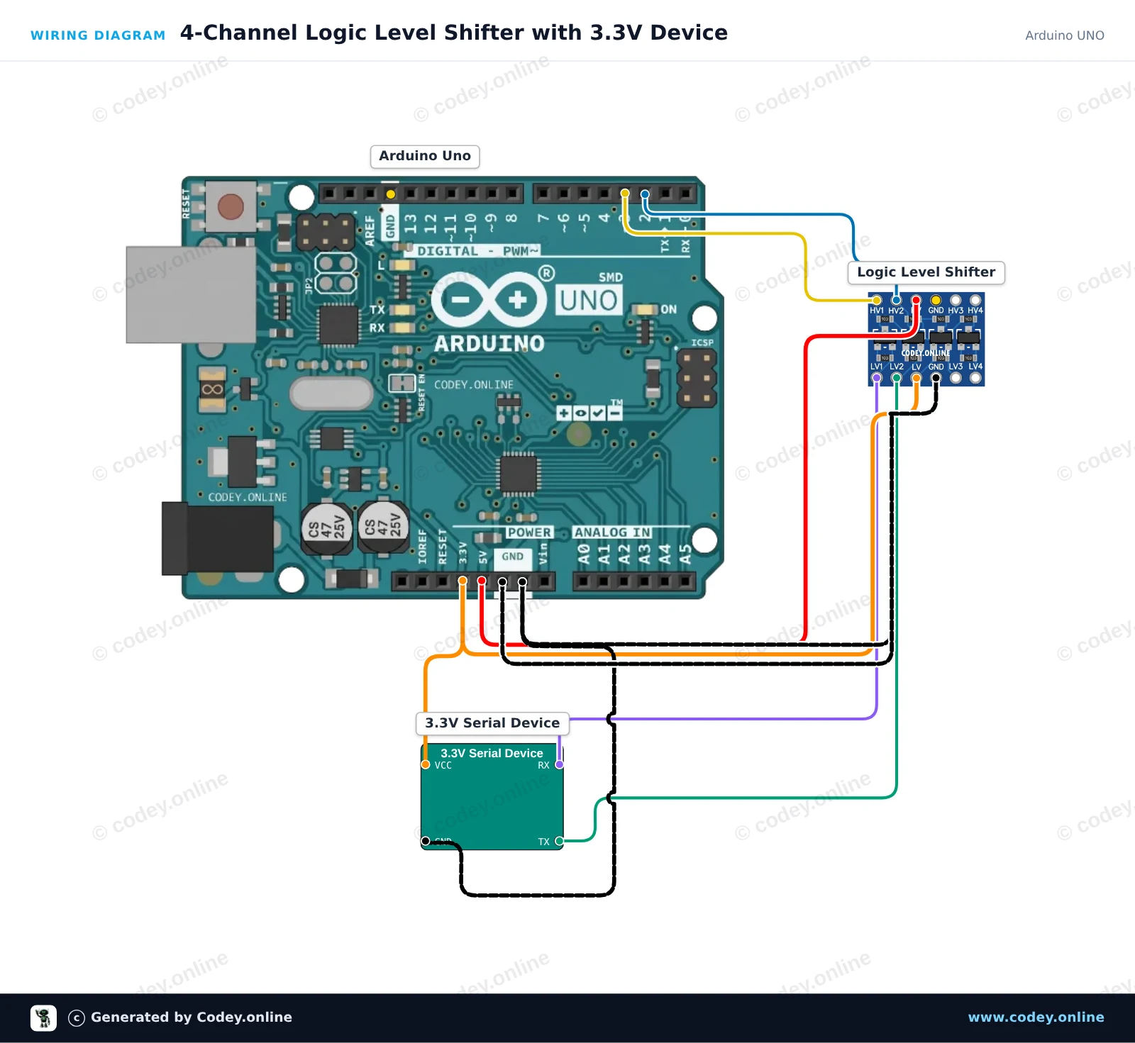
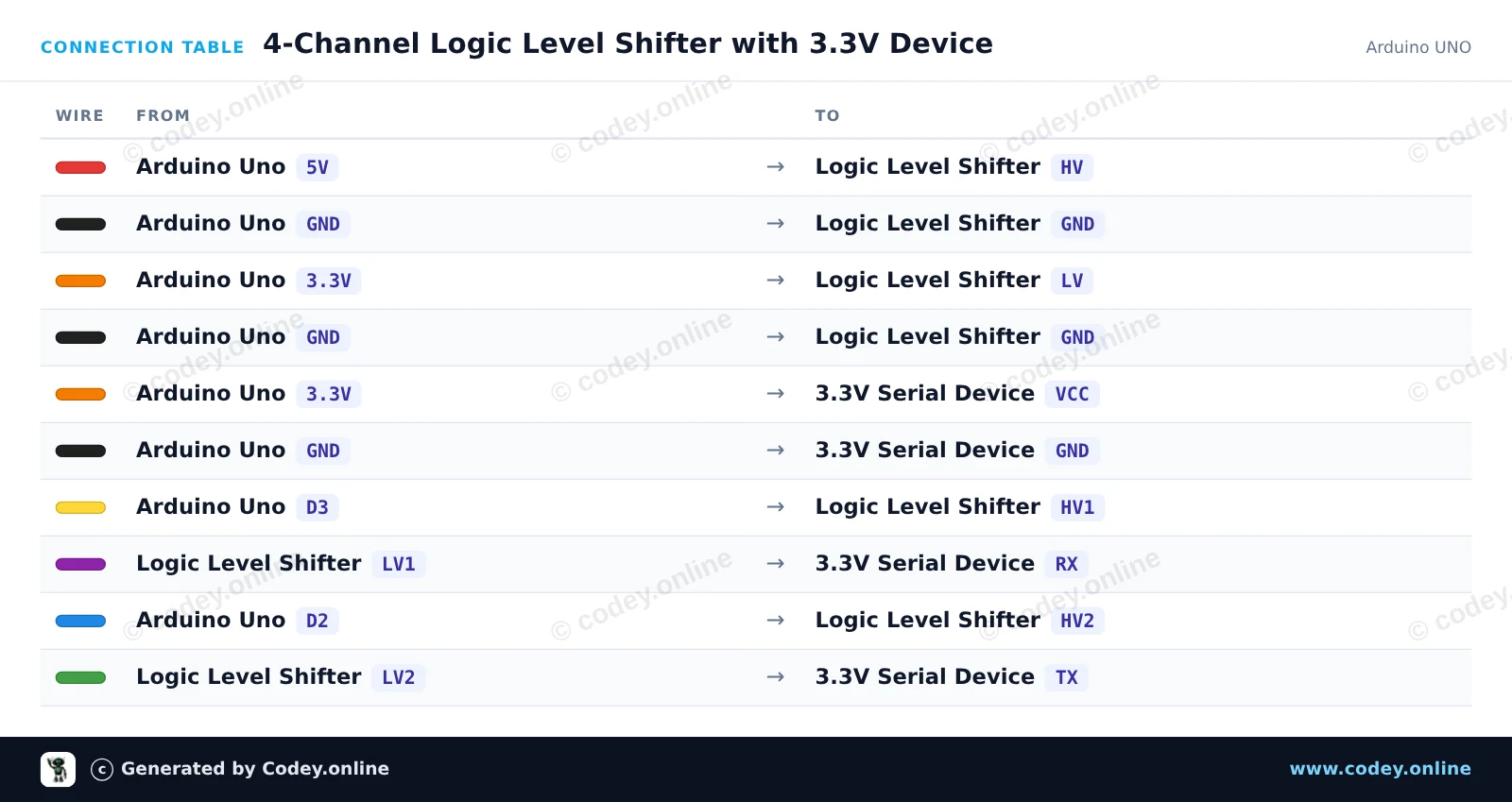
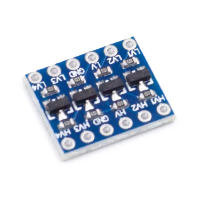
4-Channel Logic Level Shifter with 3.3V Device

This circuit safely connects the 5V Arduino Uno to a 3.3V serial device using the 4-channel bidirectional logic level shifter. The Arduino sends and receives serial data via software serial (pins 2 and 3) while the level shifter translates signals between 5V (HV) and 3.3V (LV). Open the Serial Monitor at 115200 baud to monitor communications.

Wiring diagram: I2C-UART Bi-Directional Logic Level Converter 5V-3.3V 2-channel on an Arduino UNO
Wiring diagram · Click to enlarge
Connection table: I2C-UART Bi-Directional Logic Level Converter 5V-3.3V 2-channel on an Arduino UNO
Connection table · Click to enlarge
4_Channel_Logic_Level_Shifter_with_3_3V_.ino · compiled and verified
/*
 * ==================================================================
 *  Generated by Codey.online  —  https://www.codey.online
 * ==================================================================
 *  Project   : 4-Channel Logic Level Shifter with 3.3V Device
 *  Board     : Arduino UNO (arduino:avr:uno)
 *  Parts     : Logic Level Shifter 4-channel
 *  Libraries : none (built-in)
 *
 *  Codey Online is an AI-powered browser IDE for Arduino and ESP32.
 *  Describe your project and Codey writes the code, draws the wiring
 *  diagram and uploads it to your board, straight from the browser.
 *  This code is free to use, modify and share, without warranty.
 * ==================================================================
 */

#include <SoftwareSerial.h>

// Arduino Uno pins connected to the HV (5V) side of the level shifter
const int rxPin = 2; // HV2 (receives translated 5V from 3.3V device TX)
const int txPin = 3; // HV1 (transmits 5V to be translated to 3.3V device RX)

SoftwareSerial deviceSerial(rxPin, txPin);

void setup() {
  Serial.begin(115200);
  deviceSerial.begin(9600);

  Serial.println(F("Logic Level Shifter Demo Initialized."));
  Serial.println(F("Forwarding serial data between USB and 3.3V device..."));
}

void loop() {
  // Forward data from USB Serial to 3.3V device
  if (Serial.available()) {
    char c = Serial.read();
    deviceSerial.write(c);
  }

  // Forward data from 3.3V device to USB Serial
  if (deviceSerial.available()) {
    char c = deviceSerial.read();
    Serial.write(c);
  }
}

Wiring diagram and example code generated by Codey.online — https://www.codey.online

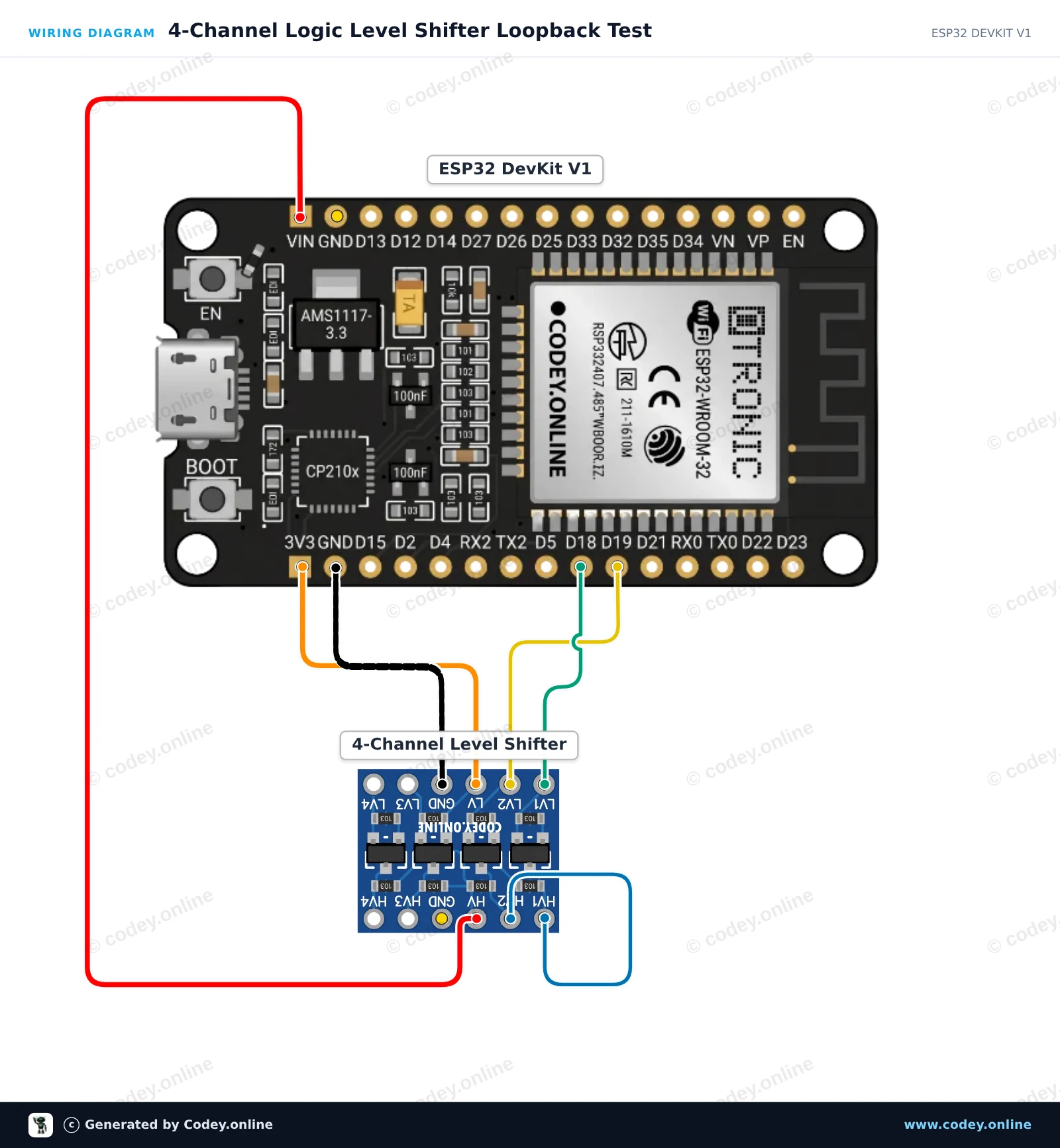
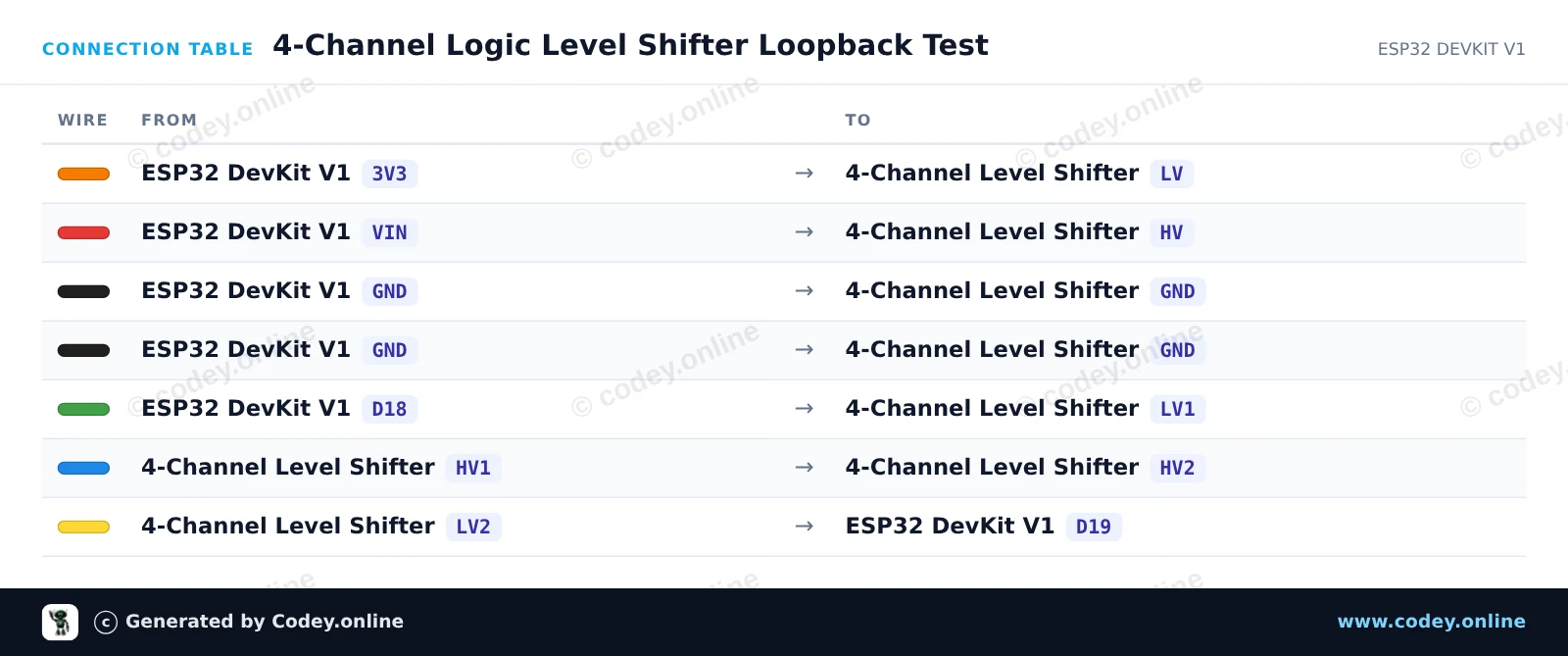
4-Channel Logic Level Shifter Loopback Test

This project demonstrates bidirectional voltage translation with the 4-channel logic level shifter. The ESP32 sends a 3.3V signal into LV1, which is stepped up to 5V at HV1. A jumper links HV1 to HV2, stepping the 5V signal back down to 3.3V at LV2 to be verified by the ESP32.

Wiring diagram: I2C-UART Bi-Directional Logic Level Converter 5V-3.3V 2-channel on an ESP32 DevKit V1
Wiring diagram · Click to enlarge
Connection table: I2C-UART Bi-Directional Logic Level Converter 5V-3.3V 2-channel on an ESP32 DevKit V1
Connection table · Click to enlarge
4_Channel_Logic_Level_Shifter_Loopback_T.ino · compiled and verified
/*
 * ==================================================================
 *  Generated by Codey.online  —  https://www.codey.online
 * ==================================================================
 *  Project   : 4-Channel Logic Level Shifter Loopback Test
 *  Board     : ESP32 DEVKIT V1 (esp32:esp32:esp32doit-devkit-v1)
 *  Parts     : Logic Level Shifter 4-channel
 *  Libraries : none (built-in)
 *
 *  Codey Online is an AI-powered browser IDE for Arduino and ESP32.
 *  Describe your project and Codey writes the code, draws the wiring
 *  diagram and uploads it to your board, straight from the browser.
 *  This code is free to use, modify and share, without warranty.
 * ==================================================================
 */

// 4-Channel Logic Level Shifter Loopback Demo
// Sends 3.3V pulses on GPIO 18 (LV1), stepped up to 5V (HV1),
// looped to HV2 (5V), and stepped down to 3.3V on LV2 to read on GPIO 19.

const int TX_PIN = 18; // 3.3V Output to LV1
const int RX_PIN = 19; // 3.3V Input from LV2

void setup() {
  Serial.begin(115200);
  while (!Serial) {
    delay(10);
  }

  pinMode(TX_PIN, OUTPUT);
  pinMode(RX_PIN, INPUT);

  Serial.println("=== Logic Level Shifter Loopback Test ===");
}

void loop() {
  // Test HIGH state
  digitalWrite(TX_PIN, HIGH);
  delay(10);
  int highRead = digitalRead(RX_PIN);

  // Test LOW state
  digitalWrite(TX_PIN, LOW);
  delay(10);
  int lowRead = digitalRead(RX_PIN);

  // Report status
  Serial.print("Sent HIGH -> Read: ");
  Serial.print(highRead == HIGH ? "HIGH [PASS]" : "LOW  [FAIL]");
  Serial.print(" | Sent LOW -> Read: ");
  Serial.println(lowRead == LOW ? "LOW  [PASS]" : "HIGH [FAIL]");

  delay(1000);
}

Wiring diagram and example code generated by Codey.online — https://www.codey.online

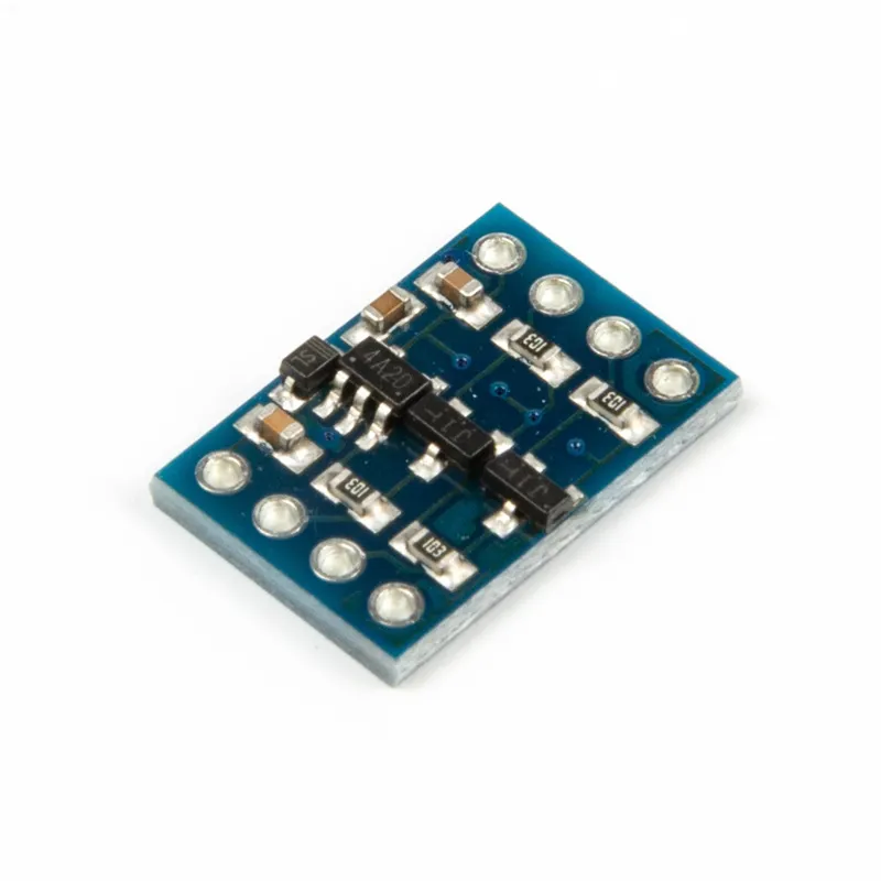
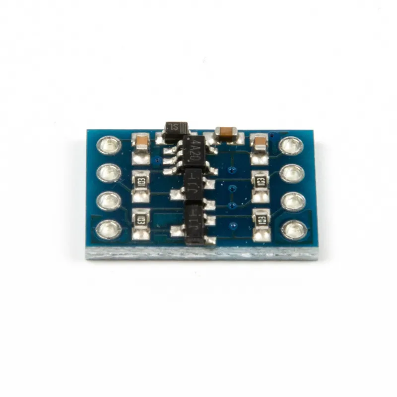
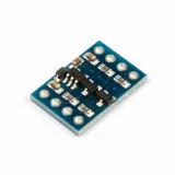
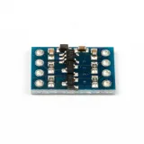
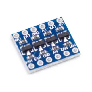
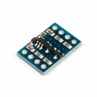
I2C-UART Bi-Directional Logic Level Converter 5V-3.3V 2-channel

Some modules operate with 3.3V I2C or UART, and this module can convert the voltage if your system operates at 5V (e.g., your 5V Arduino).

Additionally, there is a built-in voltage regulator that converts 5V to 3.3V up to 100mA, which is also useful if you need to power a module with 3.3V that does not have a built-in voltage regulator.

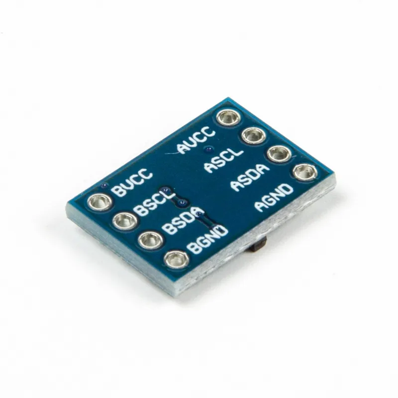
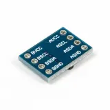
The pins are indicated on the bottom:

Connect AVCC to 5V
Connect ASCL to SCL/TX pin of 5V system
Connect ASDA to SDA/RX pin of 5V system
Connect AGND to GND of 5V system

Connect BVCC to 3.3V of system
Connect BSCL to SCL/RX pin of 3.3V system
Connect BSDA to SDA/TX pin of 3.3V system
Connect BGND to GND of 3.3V system

This module is in principle only suitable for converting from 5V to 3.3V. The voltage regulator can only convert 5V to 3.3V.
If your system is 3.3V and you want to connect a 5V module, you should connect it as follows:

Connect AVCC to 5V (5V power line)
Connect ASCL to SCL/TX pin of 5V system
Connect ASDA to SDA/RX pin of 5V system
Connect AGND to GND of 5V system

Do not connect BVCC
Connect BSCL to SCL/RX pin of 3.3V system
Connect BSDA to SDA/TX pin of 3.3V system
Connect BGND to GND of 3.3V system

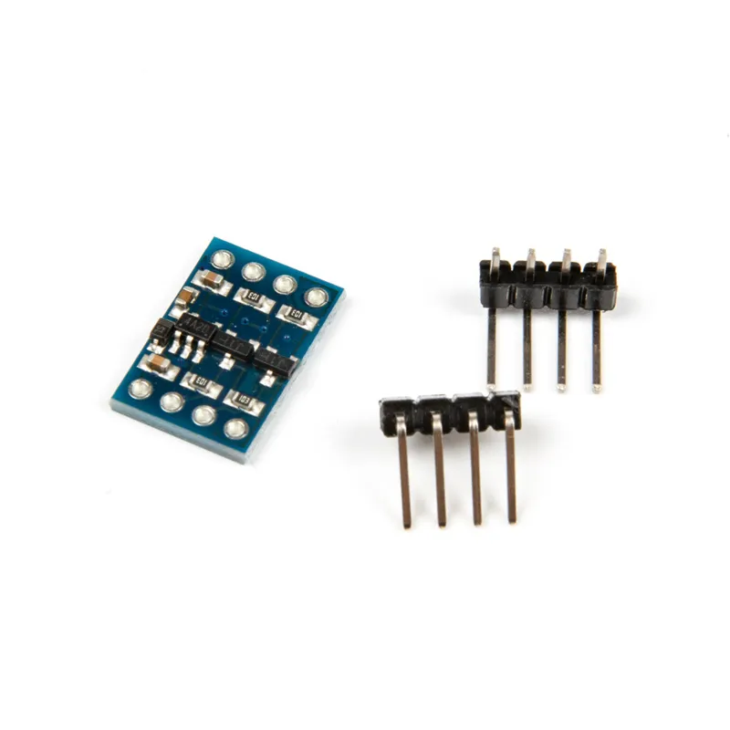
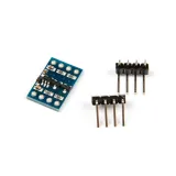
Note: The pin headers for this module are not yet soldered. If you want to use the headers, you will need to solder them yourself.

  • Voltage conversion
  • 5V to 3.3V
  • I2C and UART
  • Up to 100mA

Why choose this product?

  • Voltage conversion – Converts 5V to 3.3V
  • Useful for modules – Works with 3.3V I2C or UART
  • Built-in regulator – Supplies 3.3V up to 100mA
  • Connections listed – Pins are marked on the underside
Specifications
InterfaceI2C
Input voltage5V
Output voltage3.3 V
Power100mA

Frequently bought together

Total: € 7,25

Reviews

★★★★★ 5,0/5 2 reviews
  • ★★★★★WalterVerified purchase

    works perfectly!

  • ★★★★★Quentin Chopard

    Conforms to the description

Write a review
Your rating

Shipping & returns

Shipping

  • Parcel with track & trace€ 7,70Within 24 hours
  • Pick up at PostNL location€ 7,40Within 24 hours
  • Letterbox parcel€ 3,70Within 2 business days
  • Letterbox parcel 24 hours€ 4,55Within 24 hours
  • Pick up in storeFree
All about shipping

Returns

Not satisfied? You have 30 days after delivery to return the product.

All about returns