Op werkdagen vóór 14:00 uur besteld = dezelfde dag verzonden en in 98% van de gevallen de volgende dag in huis. Gratis retourneren 30 dagen bedenktijd 1 jaar garantie

Aansluitschema en codevoorbeeld

Zo sluit je de LED Matrix Module MAX7219 Blauw aan op een Arduino UNO of ESP32, met een voorbeeldsketch die je direct kunt uploaden.

MAX7219 8x8 LED Matrix Display Demo

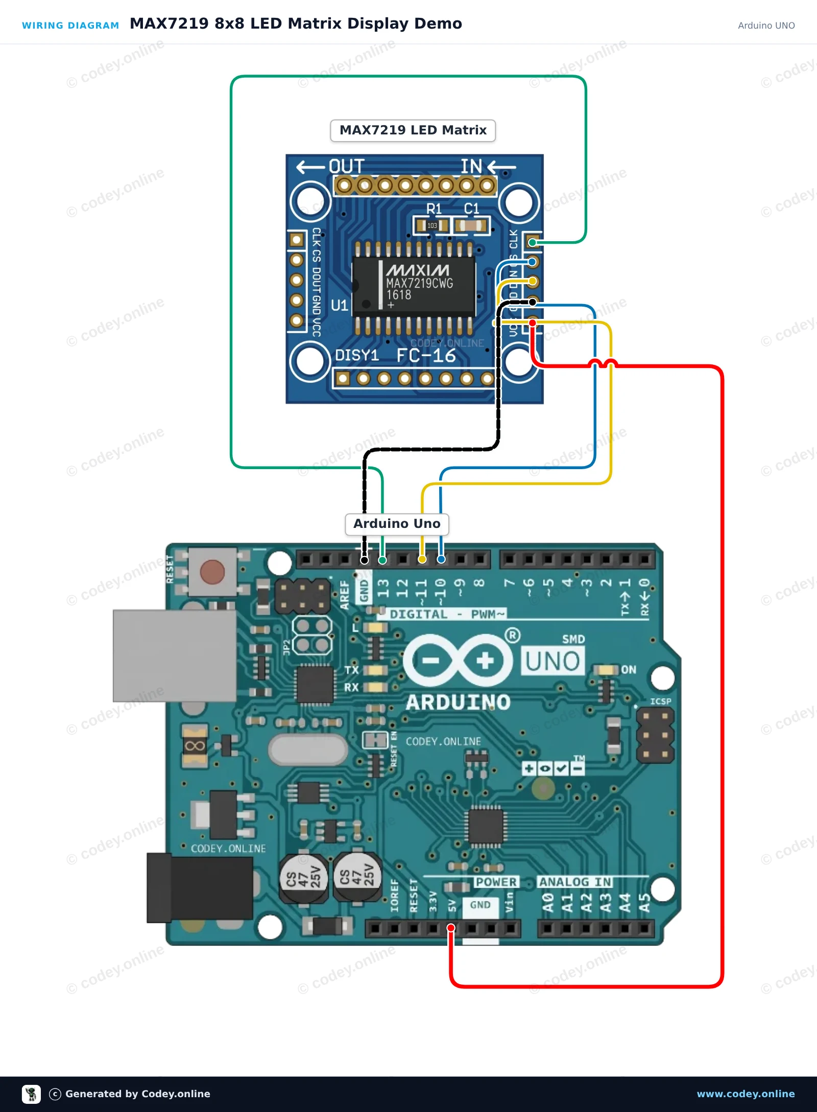
Dit project laat zien hoe je een 8x8 LED-matrix aanstuurt met de MAX7219 driverchip. De sketch activeert de matrix, stelt een comfortabele helderheid in en animeert een stuiterende stip over alle rijen en kolommen.

Aansluitschema: LED Matrix Module MAX7219 Blauw op een Arduino UNO
Aansluitschema · Klik om te vergroten
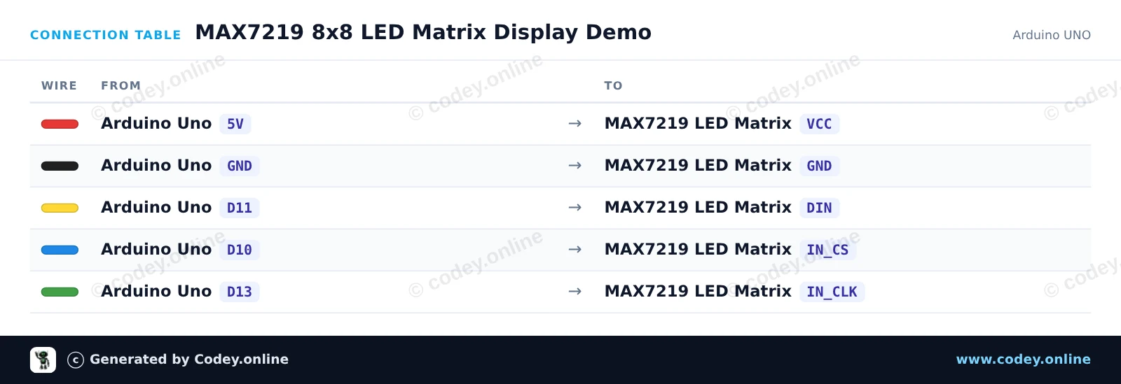
Aansluittabel: LED Matrix Module MAX7219 Blauw op een Arduino UNO
Aansluittabel · Klik om te vergroten
MAX7219_8x8_LED_Matrix_Display_Demo.ino · gecompileerd en getest
/*
 * ==================================================================
 *  Generated by Codey.online  —  https://www.codey.online
 * ==================================================================
 *  Project   : MAX7219 8x8 LED Matrix Display Demo
 *  Board     : Arduino UNO (arduino:avr:uno)
 *  Parts     : LED Matrix Module MAX7219
 *  Libraries : LedControl 1.0.6
 *
 *  Codey Online is an AI-powered browser IDE for Arduino and ESP32.
 *  Describe your project and Codey writes the code, draws the wiring
 *  diagram and uploads it to your board, straight from the browser.
 *  This code is free to use, modify and share, without warranty.
 * ==================================================================
 */

#include <LedControl.h>

const int DIN_PIN = 11;
const int CLK_PIN = 13;
const int CS_PIN  = 10;

// Create LedControl instance: LedControl(DIN, CLK, CS, number_of_matrices)
LedControl lc = LedControl(DIN_PIN, CLK_PIN, CS_PIN, 1);

// 8x8 bitmap for a smile icon
const byte SMILE[8] = {
  B00111100,
  B01000010,
  B10100101,
  B10000001,
  B10100101,
  B10011001,
  B01000010,
  B00111100
};

// 8x8 bitmap for a heart icon
const byte HEART[8] = {
  B00000000,
  B01100110,
  B11111111,
  B11111111,
  B01111110,
  B00111100,
  B00011000,
  B00000000
};

void drawBitmap(const byte bitmap[]) {
  for (int row = 0; row < 8; row++) {
    lc.setRow(0, row, bitmap[row]);
  }
}

void setup() {
  Serial.begin(115200);
  
  // Wake up MAX7219 from power-saving mode
  lc.shutdown(0, false);
  // Set medium brightness (0 to 15)
  lc.setIntensity(0, 6);
  // Clear the display
  lc.clearDisplay(0);

  Serial.println(F("MAX7219 Matrix initialized!"));
}

void loop() {
  // Display Heart
  drawBitmap(HEART);
  delay(1500);

  // Display Smile
  drawBitmap(SMILE);
  delay(1500);

  // Pixel sweep effect
  lc.clearDisplay(0);
  for (int row = 0; row < 8; row++) {
    for (int col = 0; col < 8; col++) {
      lc.setLed(0, row, col, true);
      delay(25);
      lc.setLed(0, row, col, false);
    }
  }
}

Benodigde bibliotheken: LedControl 1.0.6

Wiring diagram and example code generated by Codey.online — https://www.codey.online

MAX7219 LED-matrixdisplay met ESP32

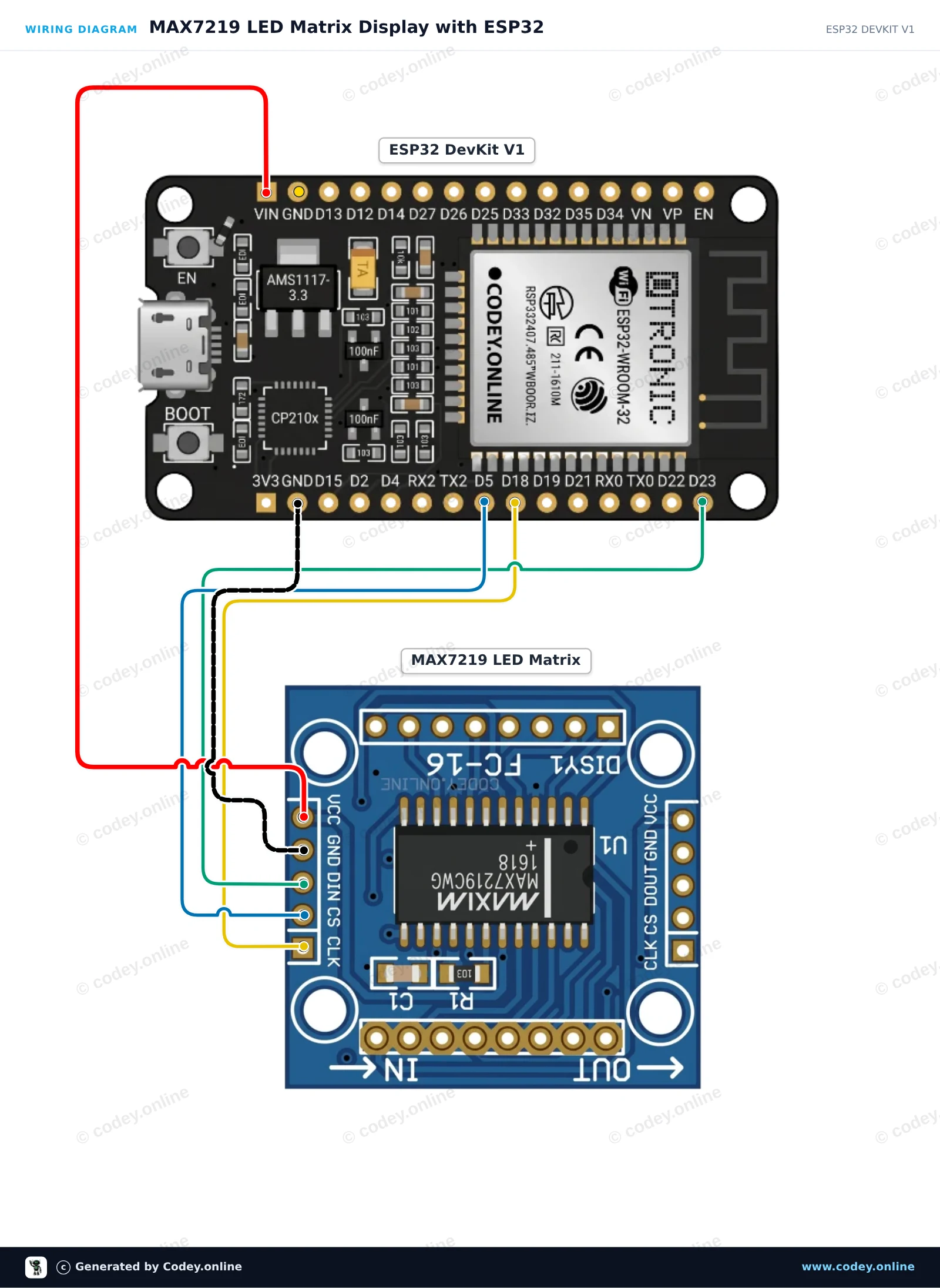
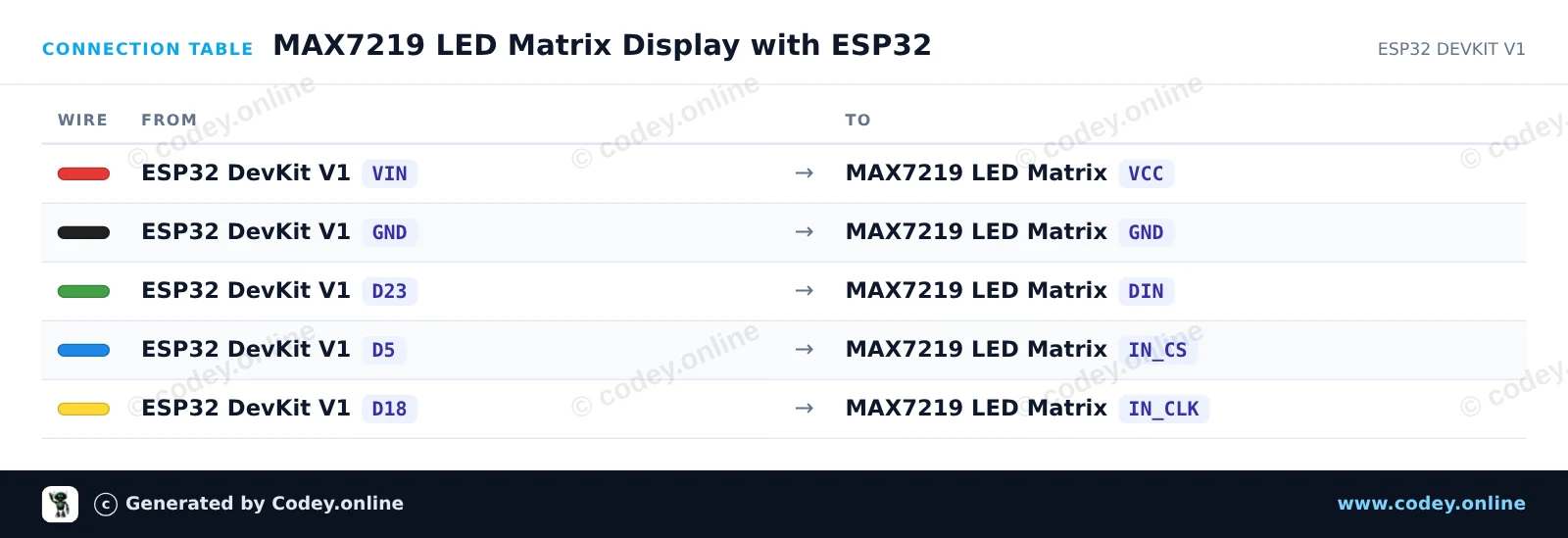
Dit project toont aangepaste patronen en animaties op een 8x8 MAX7219 LED-matrixmodule met hardware SPI. De ESP32 communiceert met de driver via GPIO 23 (MOSI/DIN), GPIO 18 (SCK/CLK) en GPIO 5 (CS), en voedt het display rechtstreeks via de 5V VIN-pin.

Aansluitschema: LED Matrix Module MAX7219 Blauw op een ESP32 DevKit V1
Aansluitschema · Klik om te vergroten
Aansluittabel: LED Matrix Module MAX7219 Blauw op een ESP32 DevKit V1
Aansluittabel · Klik om te vergroten
MAX7219_LED_Matrix_Display_with_ESP32.ino · gecompileerd en getest
/*
 * ==================================================================
 *  Generated by Codey.online  —  https://www.codey.online
 * ==================================================================
 *  Project   : MAX7219 LED Matrix Display with ESP32
 *  Board     : ESP32 DEVKIT V1 (esp32:esp32:esp32doit-devkit-v1)
 *  Parts     : LED Matrix Module MAX7219
 *  Libraries : none (built-in)
 *
 *  Codey Online is an AI-powered browser IDE for Arduino and ESP32.
 *  Describe your project and Codey writes the code, draws the wiring
 *  diagram and uploads it to your board, straight from the browser.
 *  This code is free to use, modify and share, without warranty.
 * ==================================================================
 */

#include <SPI.h>

const int CS_PIN = 5;

// MAX7219 register addresses
const byte REG_NOOP      = 0x00;
const byte REG_DECODE    = 0x09;
const byte REG_INTENSITY = 0x0A;
const byte REG_SCANLIMIT = 0x0B;
const byte REG_SHUTDOWN  = 0x0C;
const byte REG_DISPTEST  = 0x0F;

// Bitmaps for 8x8 graphics
const byte smile[8] = {
  0b00111100,
  0b01000010,
  0b10100101,
  0b10000001,
  0b10100101,
  0b10011001,
  0b01000010,
  0b00111100
};

const byte heart[8] = {
  0b00000000,
  0b01100110,
  0b11111111,
  0b11111111,
  0b11111111,
  0b01111110,
  0b00111100,
  0b00011000
};

void writeRegister(byte reg, byte data) {
  digitalWrite(CS_PIN, LOW);
  SPI.transfer(reg);
  SPI.transfer(data);
  digitalWrite(CS_PIN, HIGH);
}

void clearDisplay() {
  for (byte row = 1; row <= 8; row++) {
    writeRegister(row, 0x00);
  }
}

void drawBitmap(const byte bitmap[8]) {
  for (byte row = 0; row < 8; row++) {
    writeRegister(row + 1, bitmap[row]);
  }
}

void setup() {
  pinMode(CS_PIN, OUTPUT);
  digitalWrite(CS_PIN, HIGH);

  // Initialize hardware SPI (VSPI: SCK=18, MOSI=23)
  SPI.begin();

  // Configure MAX7219
  writeRegister(REG_DISPTEST, 0x00);  // Normal operation
  writeRegister(REG_SCANLIMIT, 0x07); // Scan all 8 digits/rows
  writeRegister(REG_DECODE, 0x00);    // No BCD decoding (raw matrix mode)
  writeRegister(REG_INTENSITY, 0x04); // Brightness (0x00 to 0x0F)
  writeRegister(REG_SHUTDOWN, 0x01);  // Wake up module

  clearDisplay();
}

void loop() {
  // Display smiley face
  drawBitmap(smile);
  delay(2000);

  // Display heart
  drawBitmap(heart);
  delay(2000);

  // Row sweep animation
  clearDisplay();
  for (byte i = 1; i <= 8; i++) {
    writeRegister(i, 0xFF);
    delay(100);
  }
  for (byte i = 1; i <= 8; i++) {
    writeRegister(i, 0x00);
    delay(100);
  }
}

Wiring diagram and example code generated by Codey.online — https://www.codey.online

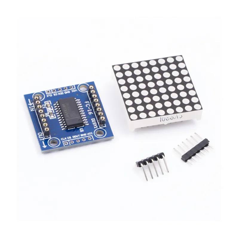
LED Matrix Module MAX7219 Blauw

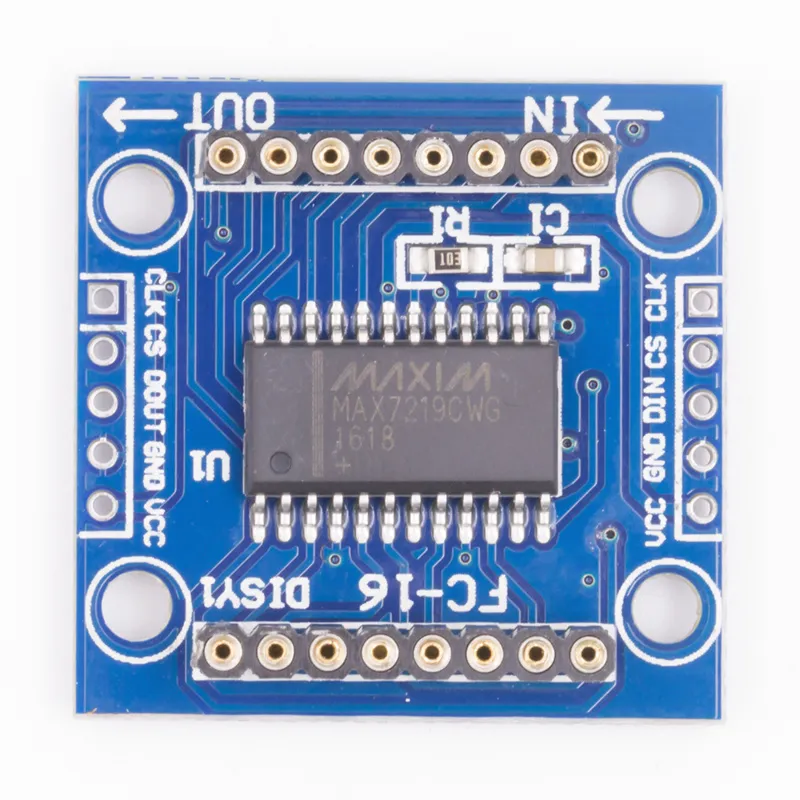
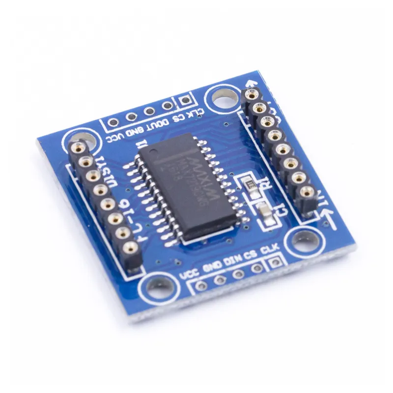
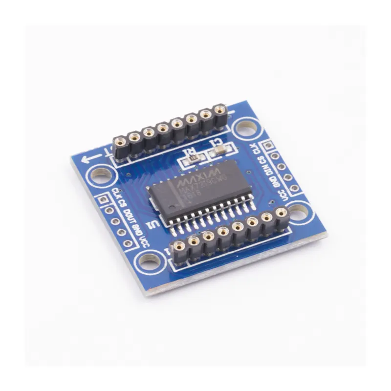
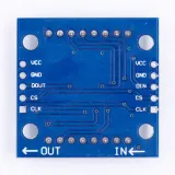
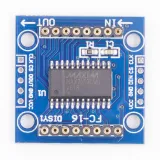
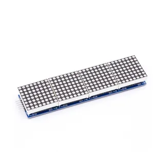
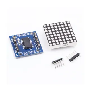
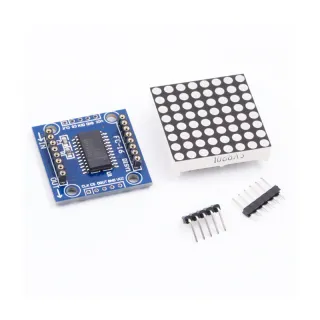
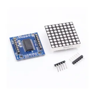
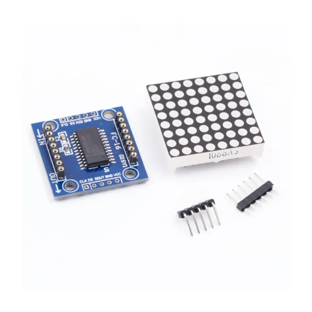
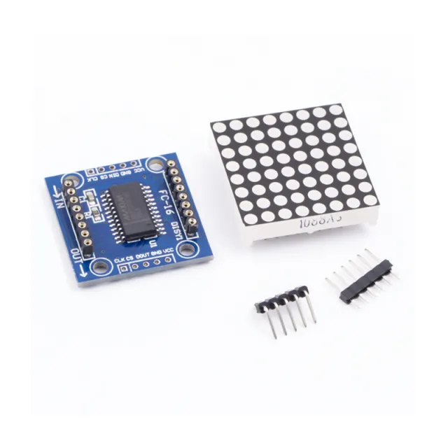
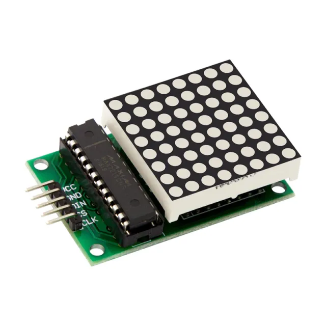
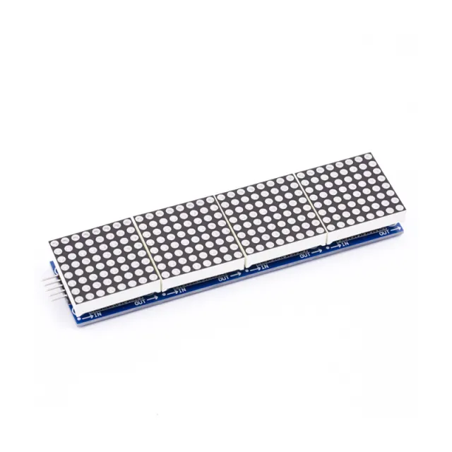
MAX7219 is een IC die wordt gebruikt voor het aansturen van LED-panelen met gemeenschappelijke kathode, displays met 7 segmenten en niveau-indicatoren die communiceren via de SPI-interface. Dit bord heeft een 8x8 dot matrix LED-display. Meerdere modules kunnen worden gecascadeerd met behulp van header-verbindingen.

Specificaties:

  • 8x8 gemeenschappelijk kathodescherm
  • Bedrijfsspanning: 5V
  • Werkstroom: 250mA (MAX)
  • Interface logica spanning: 5V
  • Interface type: SPI
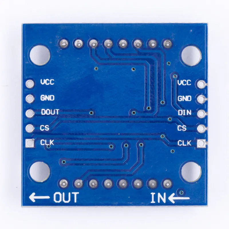
  • Verbindingen: VCC, GND, DIN, CS, CLK
  • Compatibiliteit: Compatibel met Arduino UNO R3 / Arduino Mega2560.
  • Bibliotheken voor Arduino: Max72xxPanel en Adafruit_GFX
  • LED-kleur: blauw
  • LED-maat: 5 mm
  • Aantal cascadeerbare knooppunten: 32 (MAX)
  • Driver-IC: MAX7219
  • Zeer geschikt voor Arduino DIY-projecten
  • Afmetingen: 3,2 cm x 3,2 cm x 1,3 cm
  • 4x3 mm bevestigingsgaten
  • 8x8 matrix
  • MAX7219 driver
  • SPI-interface
  • Arduino compatibel

Waarom kiezen voor dit product?

  • 8x8 display – Compact LED-matrixscherm voor projecten.
  • SPI-verbinding – Werkt via de SPI-interface.
  • Cascadeerbaar ontwerp – Meerdere modules koppelen mogelijk.
  • Arduino-compatibel – Geschikt voor UNO R3 en Mega2560.
  • Handige bibliotheken – Max72xxPanel en Adafruit_GFX inbegrepen.
Specificaties
Afmetingen3,2 cm x 3,2 cm x 1,3 cm
Bedrijfsspanning5V
CompatibiliteitCompatibel met Arduino UNO R3 / Arduino Mega2560
Driver ICMAX7219
Interface logica spanning5V
Interface typeSPI
VerbindingenVCC, GND, DIN, CS, CLK
Bibliotheken voor ArduinoMax72xxPanel en Adafruit_GFX
LED-kleurblauw
LED-maat5 mm
Aantal cascadeerbare knooppunten32 (MAX)
Schermtypegemeenschappelijk kathodescherm
Bevestigingsgaten4 x 3 mm
Werkstroom250mA (MAX)

Vaak samen gekocht

Totaal: € 14,95

Beoordelingen

★★★★★ 3,5/5 2 beoordelingen
  • ★★★★★Michel Van den AkkerGeverifieerde koop

    De helft deed het niet.

  • ★★★★★LBLM LBLMGeverifieerde koop

    Conforme à ma commande

Schrijf een beoordeling
Jouw beoordeling

Verzenden & retourneren

Verzending

  • Pakket met track & trace€ 7,70Binnen 24 uur
  • Ophalen bij PostNL locatie€ 7,40Binnen 24 uur
  • Brievenbuspakketje€ 3,70Binnen 2 werkdagen
  • Brievenbuspakketje 24 uur€ 4,55Binnen 24 uur
  • Afhalen in de winkelGratis
Alles over verzenden

Retourneren

Niet tevreden? Je hebt 30 dagen bedenktijd na ontvangst om het product terug te sturen.

Alles over retourneren

Eerder bekeken

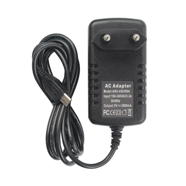
Voeding 5V 3A Micro-USB

Voeding 5V 3A Micro-USB

€ 7,49
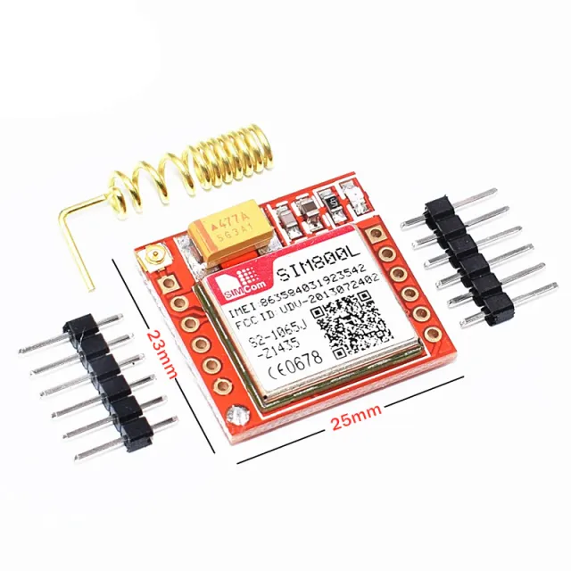
SIM800L GSM GPRS data Module

SIM800L GSM GPRS data Module

€ 6,65