Ordered on weekdays before 14:00 = shipped the same day and delivered the next day in 98% of cases. Free returns 30-day reflection period 1-year warranty

Wiring diagram and code example

How to connect the LED Matrix Module MAX7219 Blue to an Arduino UNO or ESP32, with an example sketch you can upload straight away.

MAX7219 8x8 LED Matrix Display Demo

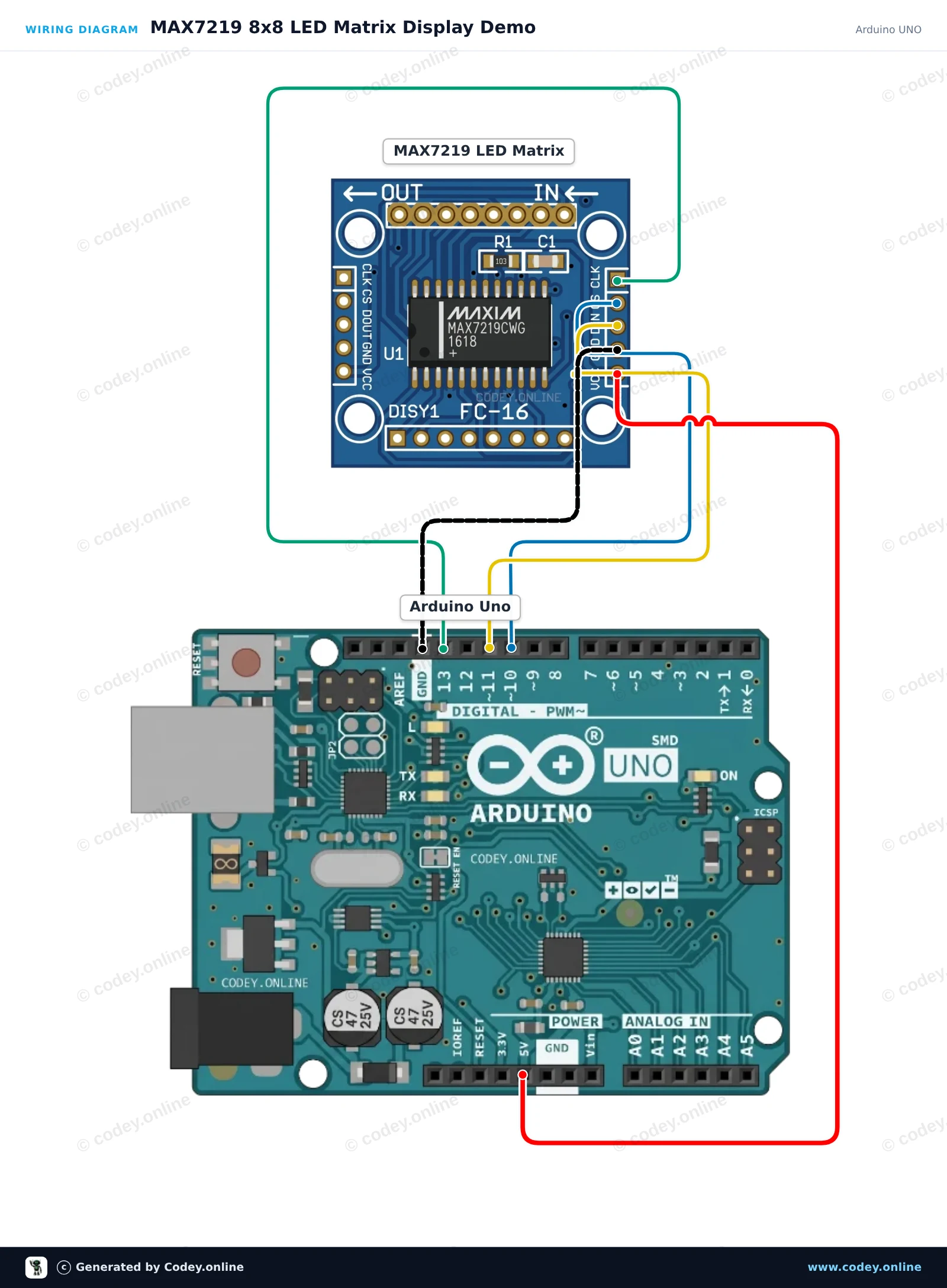
This project demonstrates how to control an 8x8 LED matrix using the MAX7219 driver chip. The sketch wakes up the matrix, sets a comfortable brightness level, and animates a bouncing dot across all rows and columns.

Wiring diagram: LED Matrix Module MAX7219 Blue on an Arduino UNO
Wiring diagram · Click to enlarge
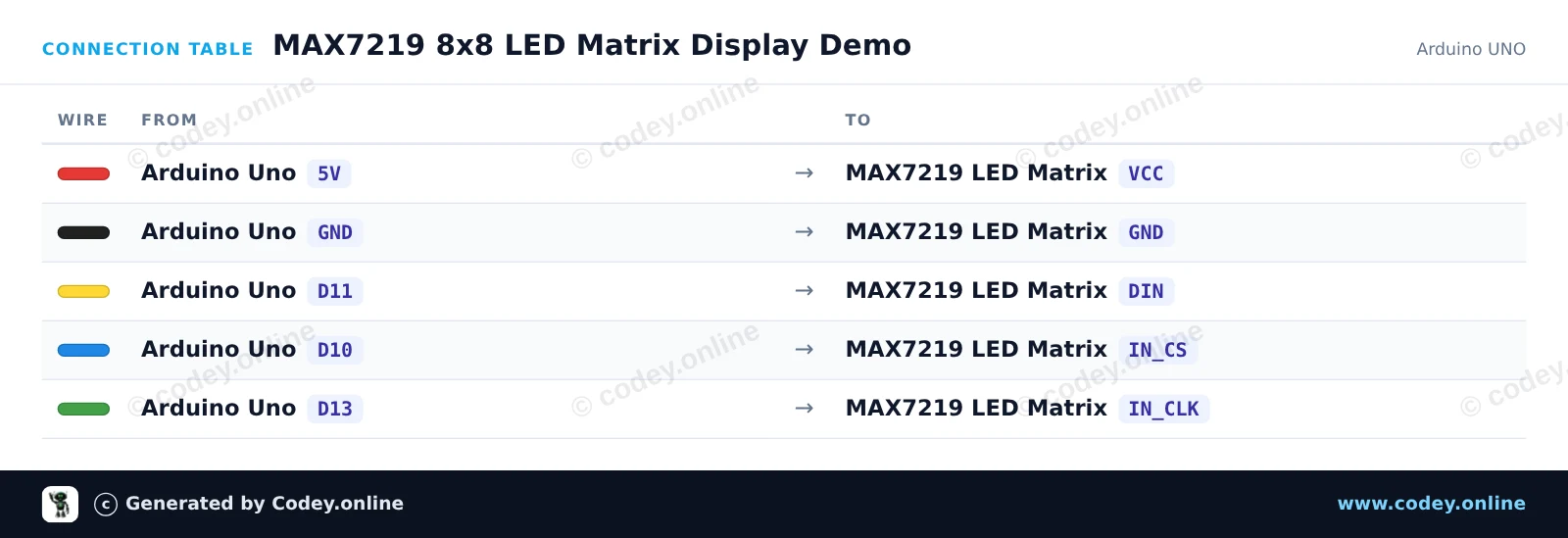
Connection table: LED Matrix Module MAX7219 Blue on an Arduino UNO
Connection table · Click to enlarge
MAX7219_8x8_LED_Matrix_Display_Demo.ino · compiled and verified
/*
 * ==================================================================
 *  Generated by Codey.online  —  https://www.codey.online
 * ==================================================================
 *  Project   : MAX7219 8x8 LED Matrix Display Demo
 *  Board     : Arduino UNO (arduino:avr:uno)
 *  Parts     : LED Matrix Module MAX7219
 *  Libraries : LedControl 1.0.6
 *
 *  Codey Online is an AI-powered browser IDE for Arduino and ESP32.
 *  Describe your project and Codey writes the code, draws the wiring
 *  diagram and uploads it to your board, straight from the browser.
 *  This code is free to use, modify and share, without warranty.
 * ==================================================================
 */

#include <LedControl.h>

const int DIN_PIN = 11;
const int CLK_PIN = 13;
const int CS_PIN  = 10;

// Create LedControl instance: LedControl(DIN, CLK, CS, number_of_matrices)
LedControl lc = LedControl(DIN_PIN, CLK_PIN, CS_PIN, 1);

// 8x8 bitmap for a smile icon
const byte SMILE[8] = {
  B00111100,
  B01000010,
  B10100101,
  B10000001,
  B10100101,
  B10011001,
  B01000010,
  B00111100
};

// 8x8 bitmap for a heart icon
const byte HEART[8] = {
  B00000000,
  B01100110,
  B11111111,
  B11111111,
  B01111110,
  B00111100,
  B00011000,
  B00000000
};

void drawBitmap(const byte bitmap[]) {
  for (int row = 0; row < 8; row++) {
    lc.setRow(0, row, bitmap[row]);
  }
}

void setup() {
  Serial.begin(115200);
  
  // Wake up MAX7219 from power-saving mode
  lc.shutdown(0, false);
  // Set medium brightness (0 to 15)
  lc.setIntensity(0, 6);
  // Clear the display
  lc.clearDisplay(0);

  Serial.println(F("MAX7219 Matrix initialized!"));
}

void loop() {
  // Display Heart
  drawBitmap(HEART);
  delay(1500);

  // Display Smile
  drawBitmap(SMILE);
  delay(1500);

  // Pixel sweep effect
  lc.clearDisplay(0);
  for (int row = 0; row < 8; row++) {
    for (int col = 0; col < 8; col++) {
      lc.setLed(0, row, col, true);
      delay(25);
      lc.setLed(0, row, col, false);
    }
  }
}

Required libraries: LedControl 1.0.6

Wiring diagram and example code generated by Codey.online — https://www.codey.online

MAX7219 LED Matrix Display with ESP32

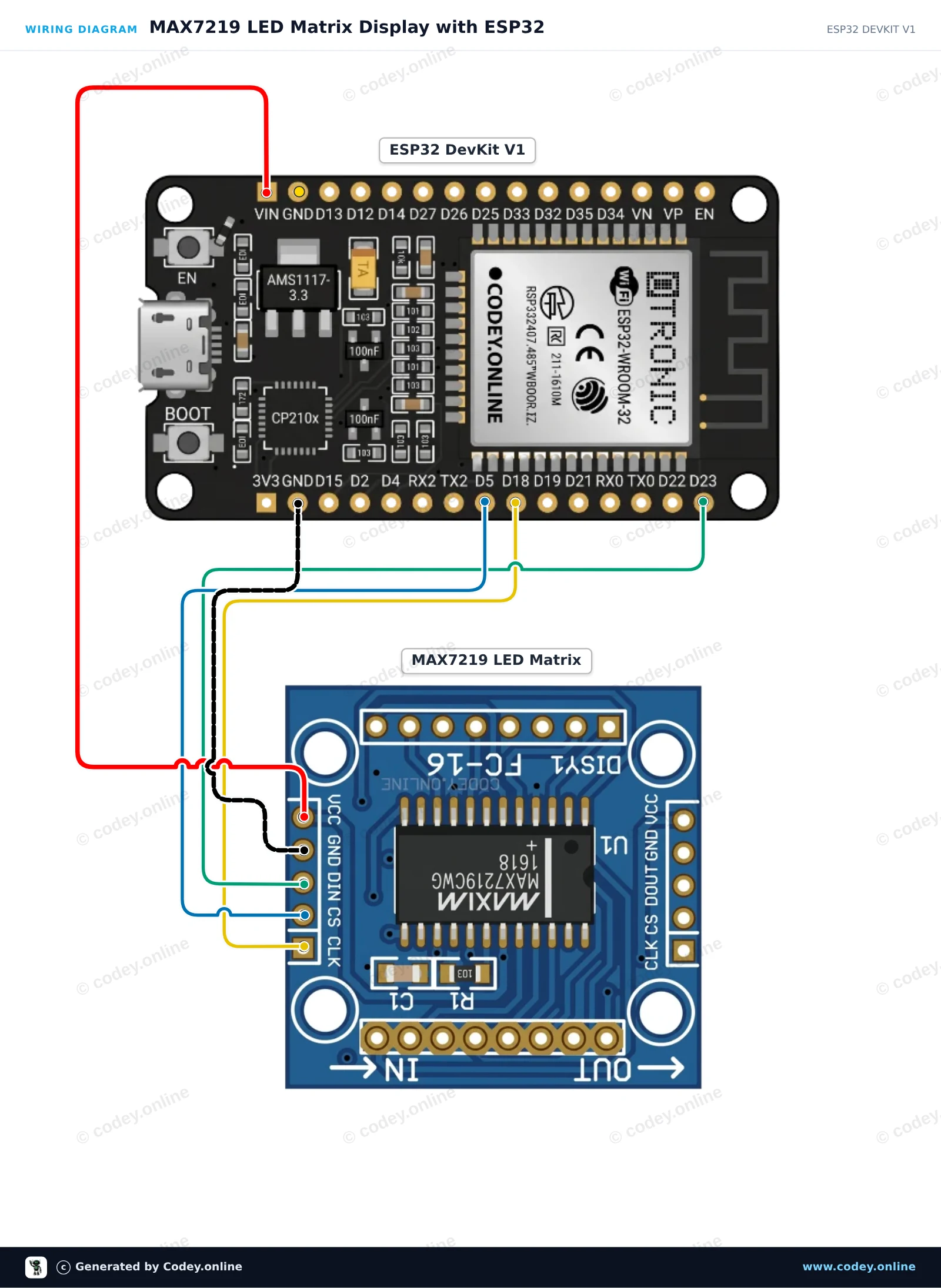
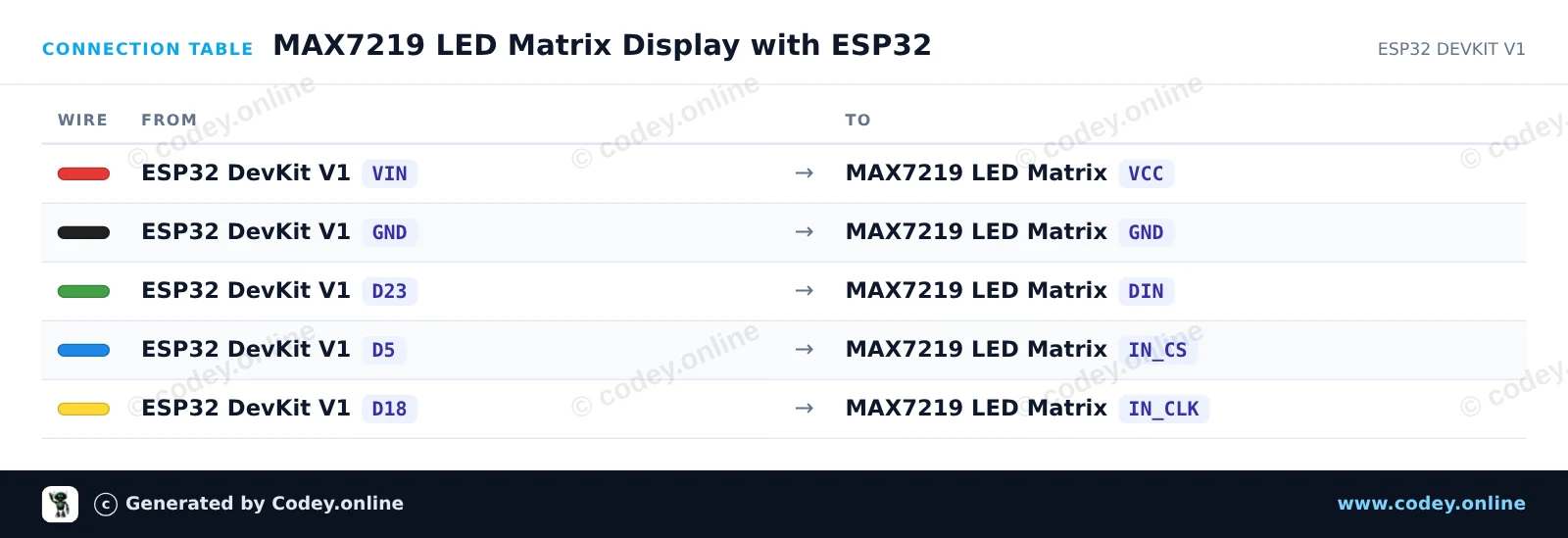
This project displays custom patterns and animations on an 8x8 MAX7219 LED matrix module using hardware SPI. The ESP32 communicates with the driver via GPIO 23 (MOSI/DIN), GPIO 18 (SCK/CLK), and GPIO 5 (CS), powering the display directly from the 5V VIN pin.

Wiring diagram: LED Matrix Module MAX7219 Blue on an ESP32 DevKit V1
Wiring diagram · Click to enlarge
Connection table: LED Matrix Module MAX7219 Blue on an ESP32 DevKit V1
Connection table · Click to enlarge
MAX7219_LED_Matrix_Display_with_ESP32.ino · compiled and verified
/*
 * ==================================================================
 *  Generated by Codey.online  —  https://www.codey.online
 * ==================================================================
 *  Project   : MAX7219 LED Matrix Display with ESP32
 *  Board     : ESP32 DEVKIT V1 (esp32:esp32:esp32doit-devkit-v1)
 *  Parts     : LED Matrix Module MAX7219
 *  Libraries : none (built-in)
 *
 *  Codey Online is an AI-powered browser IDE for Arduino and ESP32.
 *  Describe your project and Codey writes the code, draws the wiring
 *  diagram and uploads it to your board, straight from the browser.
 *  This code is free to use, modify and share, without warranty.
 * ==================================================================
 */

#include <SPI.h>

const int CS_PIN = 5;

// MAX7219 register addresses
const byte REG_NOOP      = 0x00;
const byte REG_DECODE    = 0x09;
const byte REG_INTENSITY = 0x0A;
const byte REG_SCANLIMIT = 0x0B;
const byte REG_SHUTDOWN  = 0x0C;
const byte REG_DISPTEST  = 0x0F;

// Bitmaps for 8x8 graphics
const byte smile[8] = {
  0b00111100,
  0b01000010,
  0b10100101,
  0b10000001,
  0b10100101,
  0b10011001,
  0b01000010,
  0b00111100
};

const byte heart[8] = {
  0b00000000,
  0b01100110,
  0b11111111,
  0b11111111,
  0b11111111,
  0b01111110,
  0b00111100,
  0b00011000
};

void writeRegister(byte reg, byte data) {
  digitalWrite(CS_PIN, LOW);
  SPI.transfer(reg);
  SPI.transfer(data);
  digitalWrite(CS_PIN, HIGH);
}

void clearDisplay() {
  for (byte row = 1; row <= 8; row++) {
    writeRegister(row, 0x00);
  }
}

void drawBitmap(const byte bitmap[8]) {
  for (byte row = 0; row < 8; row++) {
    writeRegister(row + 1, bitmap[row]);
  }
}

void setup() {
  pinMode(CS_PIN, OUTPUT);
  digitalWrite(CS_PIN, HIGH);

  // Initialize hardware SPI (VSPI: SCK=18, MOSI=23)
  SPI.begin();

  // Configure MAX7219
  writeRegister(REG_DISPTEST, 0x00);  // Normal operation
  writeRegister(REG_SCANLIMIT, 0x07); // Scan all 8 digits/rows
  writeRegister(REG_DECODE, 0x00);    // No BCD decoding (raw matrix mode)
  writeRegister(REG_INTENSITY, 0x04); // Brightness (0x00 to 0x0F)
  writeRegister(REG_SHUTDOWN, 0x01);  // Wake up module

  clearDisplay();
}

void loop() {
  // Display smiley face
  drawBitmap(smile);
  delay(2000);

  // Display heart
  drawBitmap(heart);
  delay(2000);

  // Row sweep animation
  clearDisplay();
  for (byte i = 1; i <= 8; i++) {
    writeRegister(i, 0xFF);
    delay(100);
  }
  for (byte i = 1; i <= 8; i++) {
    writeRegister(i, 0x00);
    delay(100);
  }
}

Wiring diagram and example code generated by Codey.online — https://www.codey.online

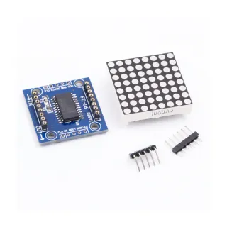
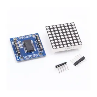
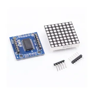
LED Matrix Module MAX7219 Blue

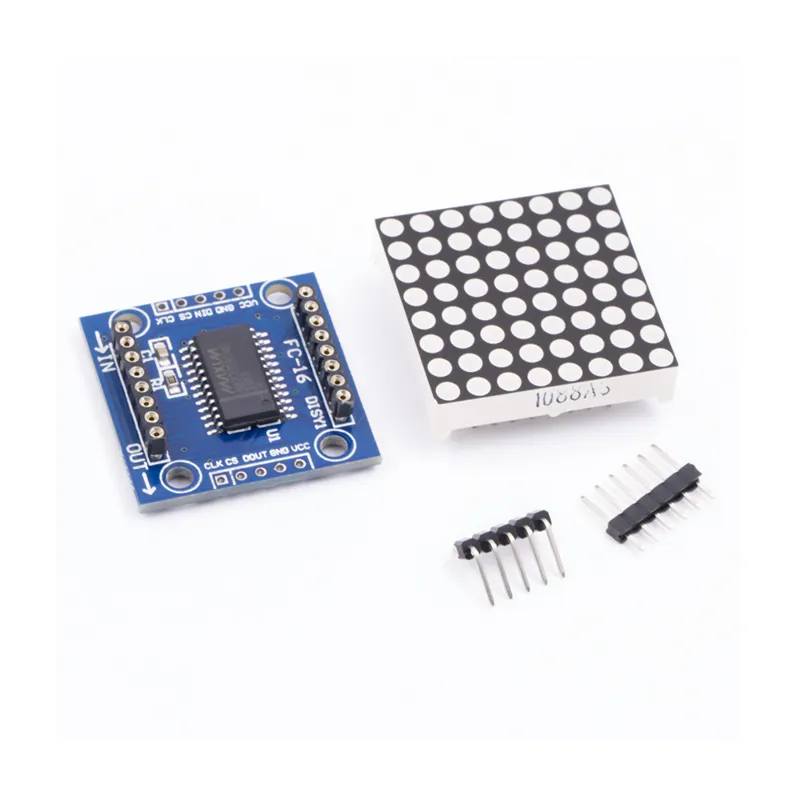
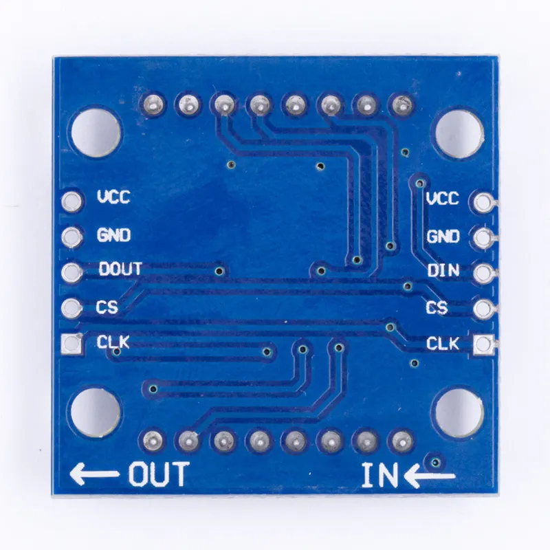
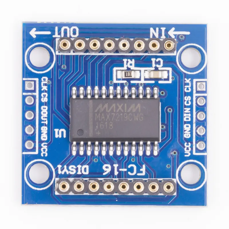
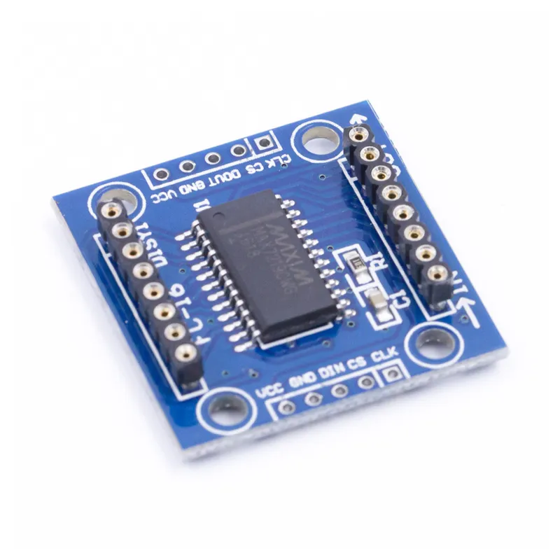
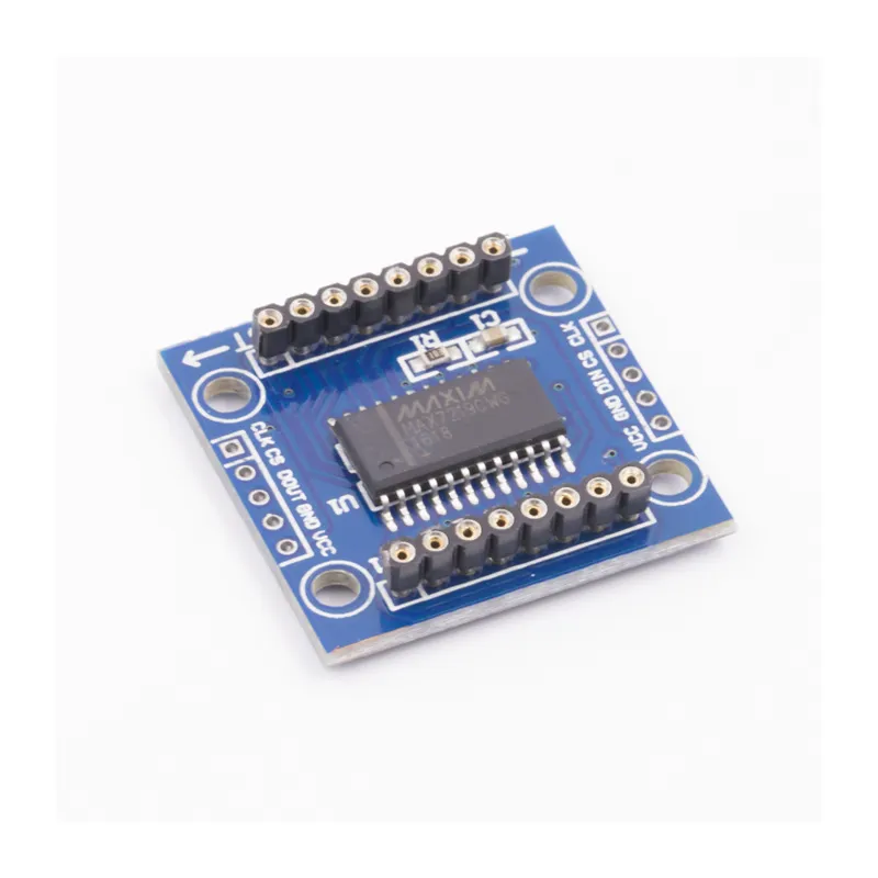
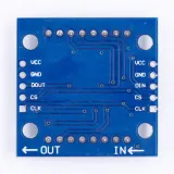
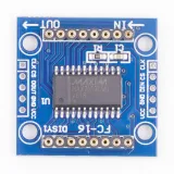
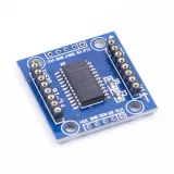
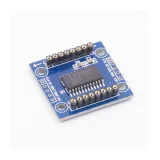
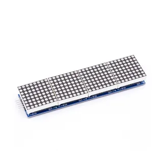
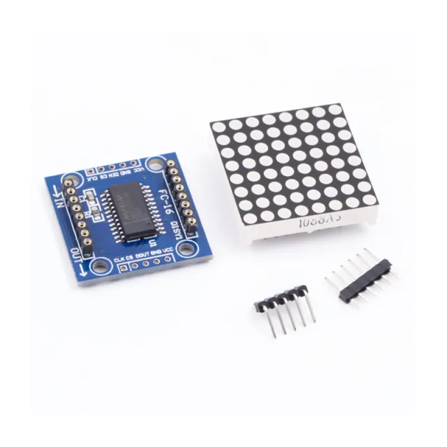
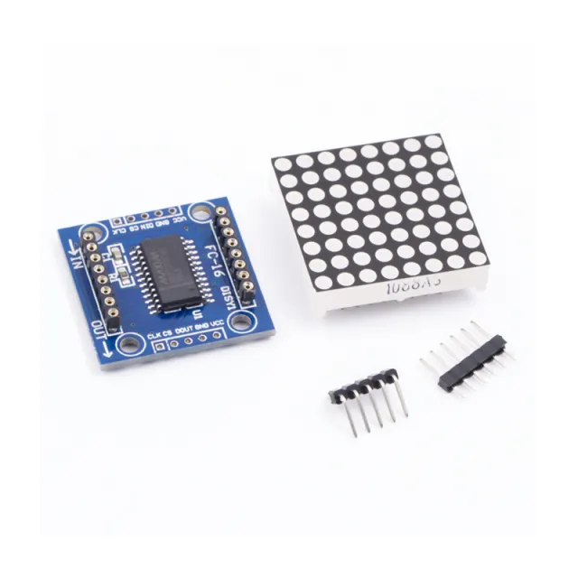
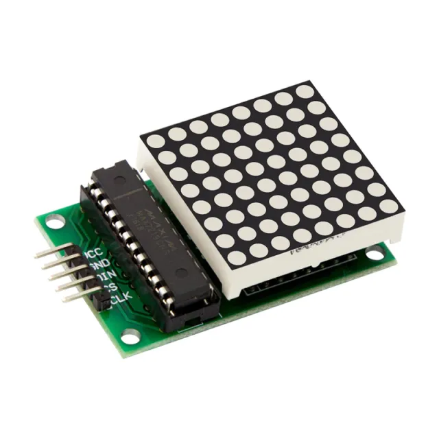
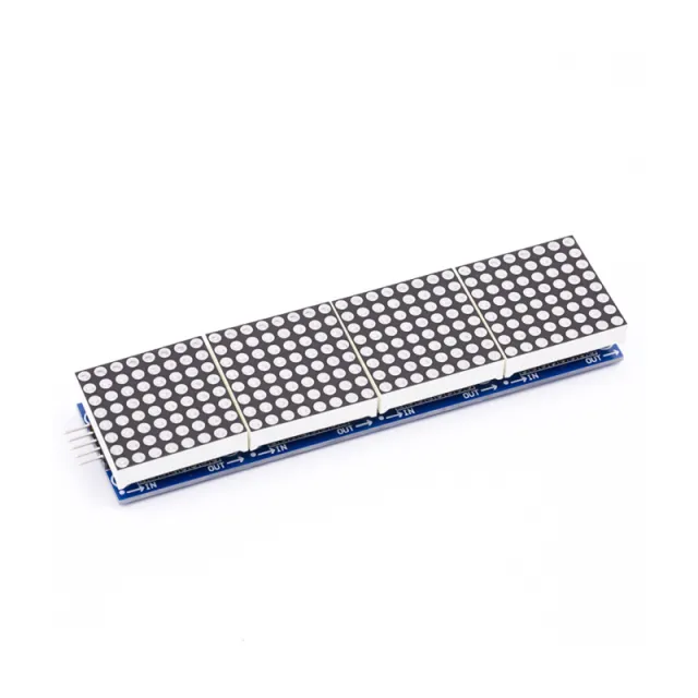
MAX7219 is an IC used for controlling LED panels with common cathode, 7-segment displays, and level indicators that communicate via the SPI interface. This board features an 8x8 dot matrix LED display. Multiple modules can be cascaded using header connections.

Specifications:

  • 8x8 common cathode display
  • Operating voltage: 5V
  • Operating current: 250mA (MAX)
  • Interface logic voltage: 5V
  • Interface type: SPI
  • Connections: VCC, GND, DIN, CS, CLK
  • Compatibility: Compatible with Arduino UNO R3 / Arduino Mega2560.
  • Libraries for Arduino: Max72xxPanel and Adafruit_GFX
  • LED color: blue
  • LED size: 5 mm
  • Number of cascadeable nodes: 32 (MAX)
  • Driver IC: MAX7219
  • Very suitable for Arduino DIY projects
  • Dimensions: 3.2 cm x 3.2 cm x 1.3 cm
  • 4x3 mm mounting holes
  • 8x8 matrix
  • MAX7219 driver
  • SPI interface
  • Arduino compatible

Why choose this product?

  • 8x8 display – Compact LED matrix display for projects.
  • SPI connection – Works via the SPI interface.
  • Daisy-chainable design – Multiple modules can be connected.
  • Arduino compatible – Suitable for UNO R3 and Mega2560.
  • Useful libraries – Max72xxPanel and Adafruit_GFX included.
Specifications
Dimensions3.2 cm x 3.2 cm x 1.3 cm
Operating voltage5V
CompatibilityCompatible with Arduino UNO R3 / Arduino Mega2560
Driver ICMAX7219
Interface logic voltage5V
Interface typeSPI
ConnectionsVCC, GND, DIN, CS, CLK
Arduino librariesMax72xxPanel and Adafruit_GFX
LED colorblue
LED size5 mm
Number of cascadeable nodes32 (MAX)
Display typecommon cathode display
Mounting holes4 x 3 mm
Operating current250mA (MAX)

Frequently bought together

Total: € 14,95

Reviews

★★★★★ 3,5/5 2 reviews
  • ★★★★★Michel Van den AkkerVerified purchase

    Half of them didn't work.

  • ★★★★★LBLM LBLMVerified purchase

    Conforms to my order

Write a review
Your rating

Shipping & returns

Shipping

  • Parcel with track & trace€ 7,70Within 24 hours
  • Pick up at PostNL location€ 7,40Within 24 hours
  • Letterbox parcel€ 3,70Within 2 business days
  • Letterbox parcel 24 hours€ 4,55Within 24 hours
  • Pick up in storeFree
All about shipping

Returns

Not satisfied? You have 30 days after delivery to return the product.

All about returns

Recently viewed

Servo S3003 360 degrees

Servo S3003 360 degrees

€ 5,70
RGB Sensor Module TCS34725

RGB Sensor Module TCS34725

€ 5,05
TCRT5000 module optical sensor

TCRT5000 module optical sensor

€ 1,60
GUVA-S12SD UV Sensor Module

GUVA-S12SD UV Sensor Module

€ 4,25
Water turbidity sensor

Water turbidity sensor

€ 13,50