SKU: OT3509 Article number: NB072 EAN: 8720618827012
From now on, your electronics will see dazzling colors with this beautiful color light sensor.
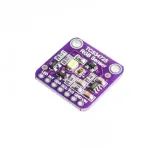
This is the best color sensor on the market, the TCS34725, which features RGB and Clear light detection elements.
An IR blocking filter enables accurate color measurements, giving you much truer color than most sensors, since humans can't see IR.
Suitable for use behind tinted glass due to the incredible dynamic range of 3,800,000:1 with adjustable integration time and gain.
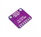
Comes with a 3.3V regulator, so you can safely power the breakout with 3-5VDC and level shifting for the I2C pins, so they can be used with 3.3V or 5V logic.
Additionally, it also features a nice neutral 4150°K temperature LED with an onboard MOSFET driver to illuminate what you're trying to sense. The LED can easily be switched on or off by a logic level output.
Connect to any microcontroller with I2C and the sample code will quickly get you started with 4-channel readings.
Connect the sensor by connecting VDD to 3-5VDC, ground to common ground, SCL to I2C Clock, and SDA to I2C data on your Arduino. Restart the IDE and select the sample sketch and put all your favorite fruit next to the sensor element!
Main features:
PACKAGE INCLUDES:
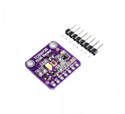
TCS34725 RGB color sensor module
Male header
The sensor works by shining a white light on an object and measuring the amount of red, green, blue, and white light reflected by the surface of that object.
The measurements are made using a 3 x 4 matrix of sensors with red/green/blue color filters in front of them. It also measures the overall intensity of the reflected light using a clear filter over three of the sensors. The entire sensor array has an IR filter over it that minimizes the effect of IR light on the measurements.
The analog sensor outputs are converted to 16-bit digital values using 4 integrating ADCs. These digital sensor values are then available to the MCU via the I2C bus.
There are 2 main settings that can be configured to influence and optimize the measurements for a particular application.
Gain Setting: The gain setting can be set to 1X, 4X, 16X, or 60X. Higher gain settings can help read the color correctly in low light, but may also increase the noise level of the measurement.
Integration Time: The integration time is the duration used for sampling. Longer integration times can provide better accuracy in some applications. The integration time for the TCS34725 Module Schematic can be set to 2.4 ms, 24 ms, 50 ms, 101 ms, 154 ms, or 700 ms.
If the interrupt is enabled and the measured values exceed an upper or lower threshold set for the interrupt, the open-collector output is driven LOW. Because it is an open-collector output, a pull-up resistor is required on the INT line to pull it HIGH when it is not being driven LOW. This can usually be implemented by enabling an internal pull-up on the uC data pin.
The built-in white LED is used to illuminate the object being measured and can be controlled via the LED pin on the module. If the pin is left floating, the LED will turn on. If you want it to be permanently off, the pin can be grounded. The pin can also be connected to a digital output on the MCU and toggled on/off when samples are taken.
I2C Interface
The module communicates via a standard I2C interface. The I2C address is fixed at address 0x29.
The module includes MOSFETs and pull-up resistors for level shifting of the I2C SDA and SCL lines, so they work correctly with both 3.3V and 5V MCUs.
Powering the module
The module can be powered by a 5V or 3.3V input on the VIN pin on the module.
The TCS34725 sensor operates at 3.3V, so a built-in 3.3V regulator steps down higher voltages to the 3.3V required for the sensor.
A 3V3 pin on the module provides access to the 3.3V output of the regulator if needed.
Module connections
LED = LED control input. Leave floating for LED always on. Pull LOW to disable the LED
INT = Interrupt output active LOW. Output is open-collector so requires pull-up resistor. Connects to an interrupt input on the MCU, if used.
SDA = I2C SDA line. Connects to SDA on MCU
SCL = I2C SCL line. Connects to SCL on MCU
3V3 = 3.3V output from the built-in 3.3V regulator
GND = ground connects to ground on the MCU
VIN = Supply voltage. Connects to 3.3V or 5V on the MCU
Module assembly
The module comes with the male header strip loose. This allows the header to be soldered to either the top or bottom of the module depending on the intended use, or wires can be used to make the connections.
For breadboard use, we place the headers on the bottom. Soldering is easiest if the header is inserted into a breadboard to hold it in place during the soldering process.