Ordered on weekdays before 14:00 = shipped the same day and delivered the next day in 98% of cases. Free returns 30-day reflection period 1-year warranty

Wiring diagram and code example

How to connect the 12V adjustable time delay relay module to an Arduino UNO or ESP32, with an example sketch you can upload straight away.

Adjustable Timer Delay Relay Trigger

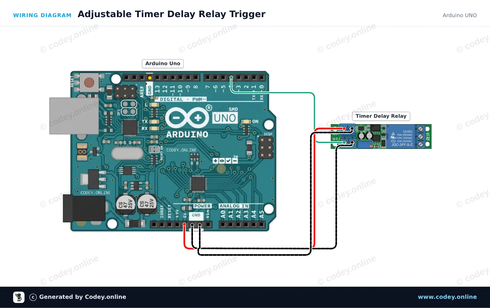
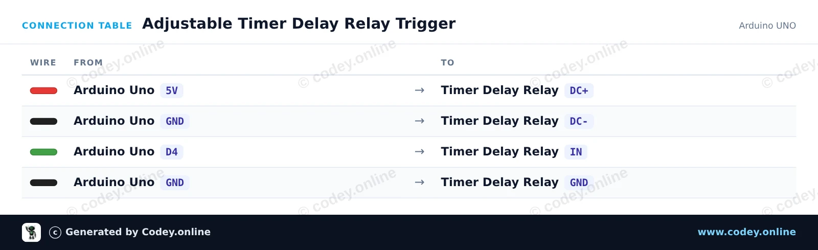
This project demonstrates how to trigger an adjustable timer delay relay module using an Arduino Uno. The Arduino sends a short pulse from digital pin 4 to the IN trigger pin, activating the onboard timer delay cycle. Adjust the potentiometer on the relay module to change the duration of the relay activation.

Wiring diagram: 12V adjustable time delay relay module on an Arduino UNO
Wiring diagram · Click to enlarge
Connection table: 12V adjustable time delay relay module on an Arduino UNO
Connection table · Click to enlarge
Adjustable_Timer_Delay_Relay_Trigger.ino · compiled and verified
/*
 * ==================================================================
 *  Generated by Codey.online  —  https://www.codey.online
 * ==================================================================
 *  Project   : Adjustable Timer Delay Relay Trigger
 *  Board     : Arduino UNO (arduino:avr:uno)
 *  Parts     : DC 12V adjustable timer delay, time delay relay turn off switch module time relay time switch 0~25sec for smart home, automatic control
 *  Libraries : none (built-in)
 *
 *  Codey Online is an AI-powered browser IDE for Arduino and ESP32.
 *  Describe your project and Codey writes the code, draws the wiring
 *  diagram and uploads it to your board, straight from the browser.
 *  This code is free to use, modify and share, without warranty.
 * ==================================================================
 */

// Timer Delay Relay Module Demo
// Sends a trigger pulse to start the module's countdown delay.

const int triggerPin = 4;

void setup() {
  pinMode(triggerPin, OUTPUT);
  digitalWrite(triggerPin, LOW);

  Serial.begin(115200);
  Serial.println(F("Timer Delay Relay Demo Initialized."));
}

void loop() {
  Serial.println(F("Triggering relay delay cycle..."));
  
  // Send a 200 ms HIGH pulse to trigger the module
  digitalWrite(triggerPin, HIGH);
  delay(200);
  digitalWrite(triggerPin, LOW);
  
  Serial.println(F("Trigger sent. Waiting for delay cycle to complete..."));
  
  // Wait 10 seconds before triggering the next cycle
  delay(10000);
}

Wiring diagram and example code generated by Codey.online — https://www.codey.online

Trigger 12V Adjustable Timer Delay Relay

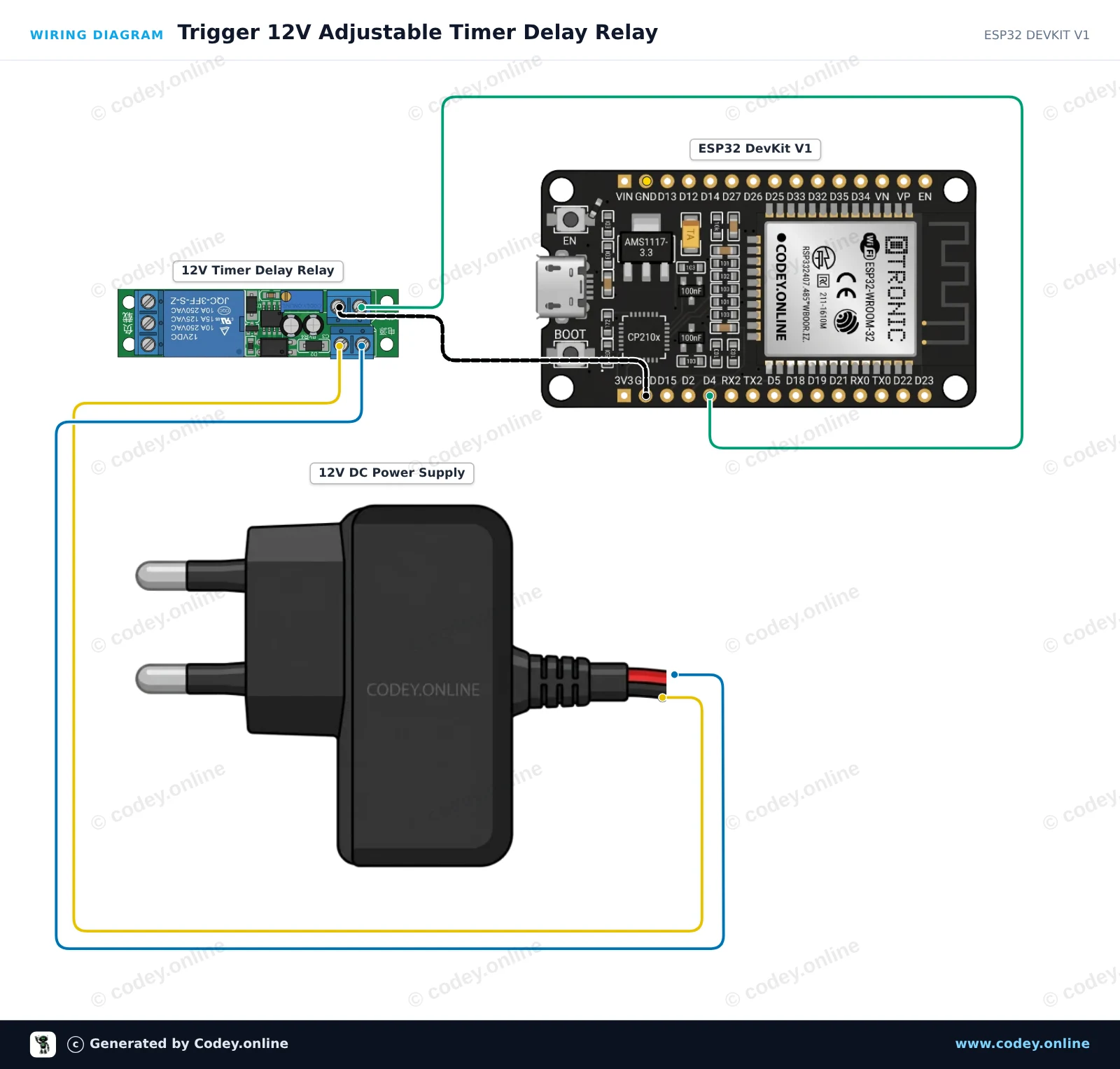
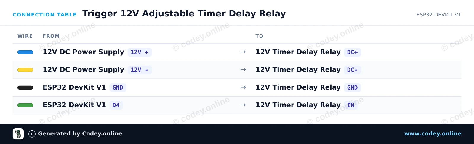
This project demonstrates triggering an adjustable 12V time delay relay module using an ESP32. The ESP32 sends a short trigger pulse to start the countdown, and the relay stays energized for the duration set by the onboard potentiometer (0 to 25 seconds).

Wiring diagram: 12V adjustable time delay relay module on an ESP32 DevKit V1
Wiring diagram · Click to enlarge
Connection table: 12V adjustable time delay relay module on an ESP32 DevKit V1
Connection table · Click to enlarge
Trigger_12V_Adjustable_Timer_Delay_Relay.ino · compiled and verified
/*
 * ==================================================================
 *  Generated by Codey.online  —  https://www.codey.online
 * ==================================================================
 *  Project   : Trigger 12V Adjustable Timer Delay Relay
 *  Board     : ESP32 DEVKIT V1 (esp32:esp32:esp32doit-devkit-v1)
 *  Parts     : DC 12V adjustable timer delay, time delay relay turn off switch module time relay time switch 0~25sec for smart home, automatic control
 *  Libraries : none (built-in)
 *
 *  Codey Online is an AI-powered browser IDE for Arduino and ESP32.
 *  Describe your project and Codey writes the code, draws the wiring
 *  diagram and uploads it to your board, straight from the browser.
 *  This code is free to use, modify and share, without warranty.
 * ==================================================================
 */

// Pin connected to the IN trigger pin of the timer relay module
const int TRIGGER_PIN = 4;

void setup() {
  Serial.begin(115200);
  pinMode(TRIGGER_PIN, OUTPUT);
  digitalWrite(TRIGGER_PIN, LOW);
  
  Serial.println("ESP32 12V Timer Delay Relay Module Initialized");
  delay(1000);
}

void loop() {
  Serial.println("Sending trigger pulse...");
  
  // Send a 200 ms pulse to activate the timer
  digitalWrite(TRIGGER_PIN, HIGH);
  delay(200);
  digitalWrite(TRIGGER_PIN, LOW);
  
  Serial.println("Triggered! The relay will remain active for the duration set by the potentiometer.");
  
  // Wait 15 seconds before triggering the next cycle
  delay(15000);
}

Wiring diagram and example code generated by Codey.online — https://www.codey.online

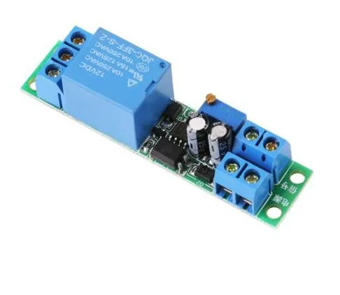
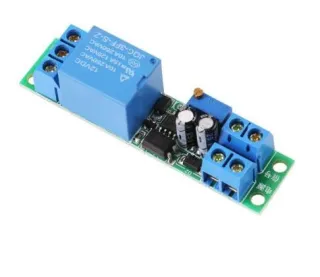
12V adjustable time delay relay module

This time-delay relay module operates on 12V and can be adjusted using the trimmer potentiometer.

Operating voltage: DC 12V
Current consumption (when switched on): ~46mA
Maximum voltage through relay: 30VDC or 250VAC
Maximum current through relay: 10A
Adjustable delay between 0.1 and 25 seconds

For instructions and a wiring diagram, we have the OTRONIC Quick Start Guide for the 12V adjustable time delay relay module available for you.

Instructions:
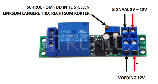
This OTRONIC® adjustable time delay relay module has an adjustable delay for switch-off (drop-out).

width=660

Testing the relay
You can test the set time of the relay without an external control signal.
Connect 12V power supply to VCC and GND (Power supply). Without a signal, the relay will perform the
time delay once. You can hear this by the click of the relay.
Use the trimmer potentiometer to adjust the time. Turn counterclockwise for a longer time and clockwise
for a shorter time.
NOTE: Multiple turns of the trimmer are required to adjust the time.

Dimensions
Length: 6.68cm
Width: 1.6cm
Height: 1.68cm

  • Adjustable delay
  • 12V operation
  • 0.1-25 s
  • Compact size

Why choose this product?

  • Adjustable delay – Time adjustable from 0.1 to 25 seconds.
  • Switch-off delay – For drop-out with delayed switch-off.
  • Test without control signal – Test the set time directly.
  • Easy to adjust – With screw potentiometer left or right.
Specifications
Width1,6 cm
Operating voltageDC 12V
Length6,68 cm
Power consumption~46mA
Height1,68 cm
Power10A
Time delay0.1 - 25 s

Frequently bought together

Total: € 17,59

Reviews

★★★★★ 4,7/5 12 reviews
  • ★★★★★w verboorVerified purchase

    This was what I meant

  • ★★★★★ACH

    Too small

  • ★★★★★Jean-Marie CLEMENCEAUVerified purchase

    May need some more description and electrical drawing

Write a review
Your rating

Shipping & returns

Shipping

  • Parcel with track & trace€ 7,70Within 24 hours
  • Pick up at PostNL location€ 7,40Within 24 hours
  • Letterbox parcel€ 3,70Within 2 business days
  • Letterbox parcel 24 hours€ 4,55Within 24 hours
  • Pick up in storeFree
All about shipping

Returns

Not satisfied? You have 30 days after delivery to return the product.

All about returns

Recently viewed

Water turbidity sensor

Water turbidity sensor

€ 13,50
ESP-01 ESP8266 module

ESP-01 ESP8266 module

€ 3,75
Solid State Relay Module 5V

Solid State Relay Module 5V

€ 2,35