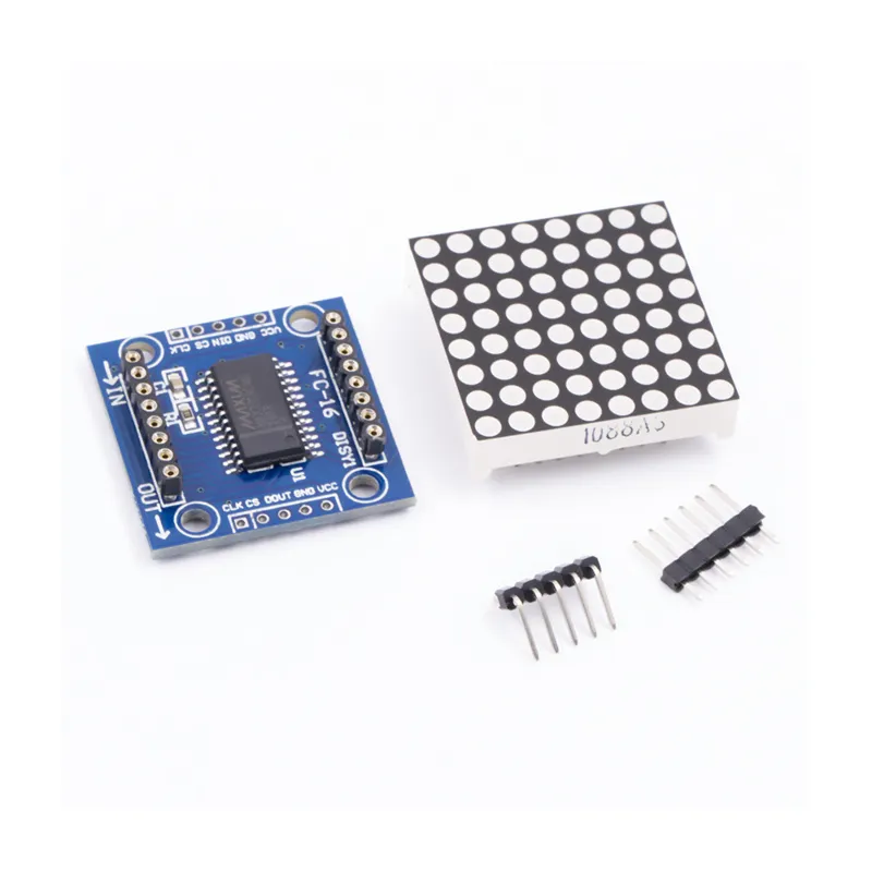
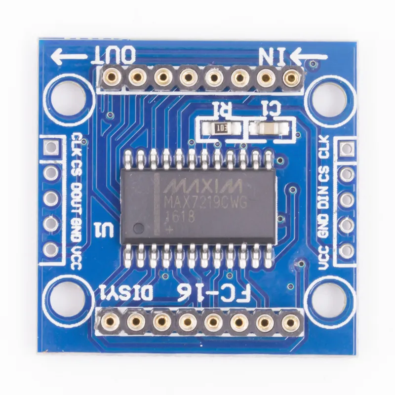
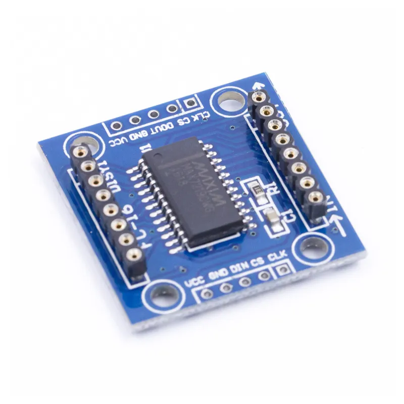
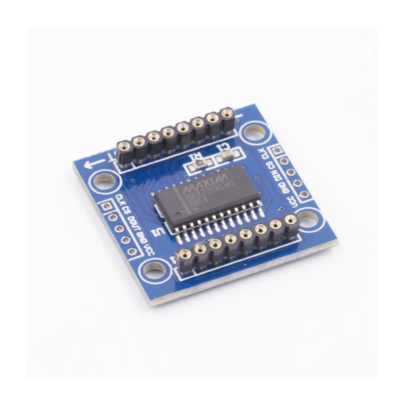
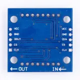
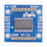
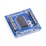
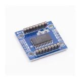
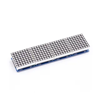
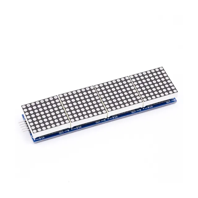
8x8 LED-matrixmodule voor Arduino DIY-projecten met SPI-aansturing en cascadeerbare modules.
SKU: OT3643 Artikelnummer: AA185 EAN: 8720618489722 Locatie: H05.05
Alternatief
LED Matrix 32x8 met MAX7219 Module
€ 6,25
Bekijk dit alternatief
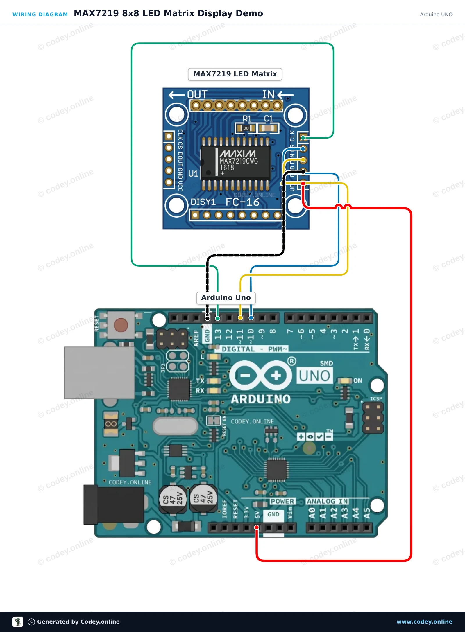
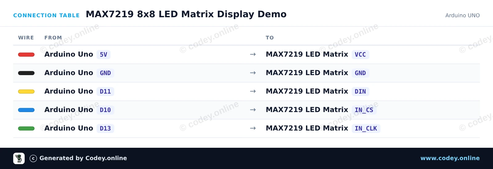
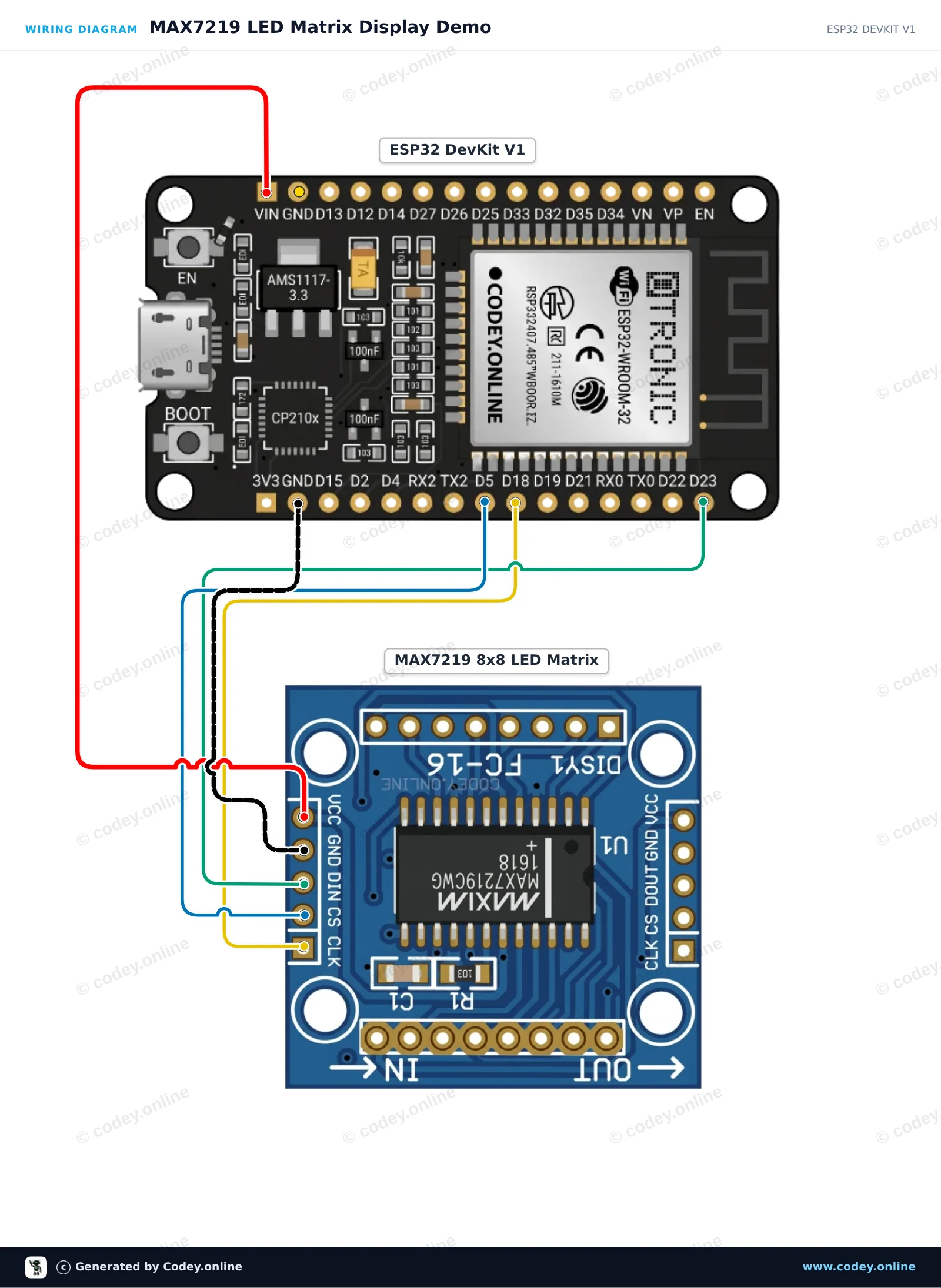
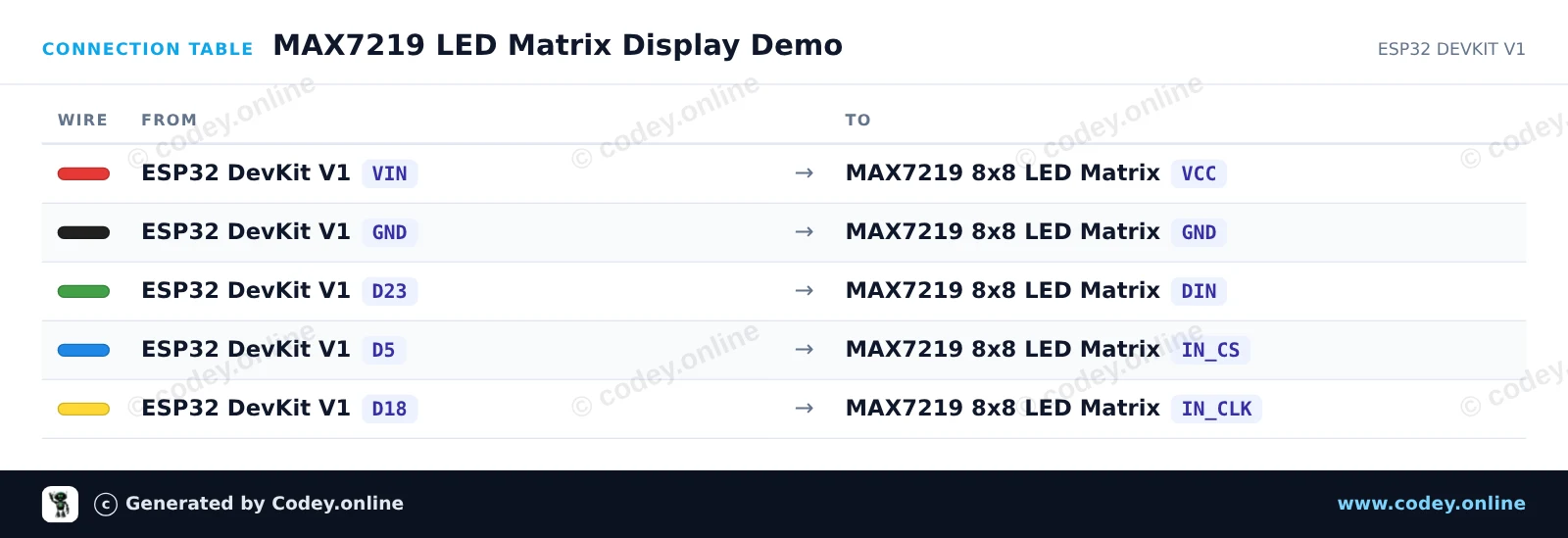
Zo sluit je de LED Matrix Module MAX7219 Rood aan op een Arduino UNO of ESP32, met een voorbeeldsketch die je direct kunt uploaden.
Dit project laat zien hoe je een 8x8 LED-matrix aanstuurt met de MAX7219 driver chip. Het initialiseert het display en laat achtereenvolgens een smiley, een hartpictogram en een scannend pixelpatroon zien.
/*
* ==================================================================
* Generated by Codey.online — https://www.codey.online
* ==================================================================
* Project : MAX7219 8x8 LED Matrix Display Demo
* Board : Arduino UNO (arduino:avr:uno)
* Parts : LED Matrix Module MAX7219
* Libraries : LedControl 1.0.6
*
* Codey Online is an AI-powered browser IDE for Arduino and ESP32.
* Describe your project and Codey writes the code, draws the wiring
* diagram and uploads it to your board, straight from the browser.
* This code is free to use, modify and share, without warranty.
* ==================================================================
*/
#include <LedControl.h>
const int DIN_PIN = 11;
const int CS_PIN = 10;
const int CLK_PIN = 13;
LedControl lc = LedControl(DIN_PIN, CLK_PIN, CS_PIN, 1);
// 8x8 bitmap patterns
const byte SMILEY[8] = {
0b00111100,
0b01000010,
0b10100101,
0b10000001,
0b10100101,
0b10011001,
0b01000010,
0b00111100
};
const byte HEART[8] = {
0b00000000,
0b01100110,
0b11111111,
0b11111111,
0b01111110,
0b00111100,
0b00011000,
0b00000000
};
void drawPattern(const byte pattern[8]) {
for (int row = 0; row < 8; row++) {
lc.setRow(0, row, pattern[row]);
}
}
void setup() {
Serial.begin(115200);
Serial.println(F("MAX7219 LED Matrix Demo"));
lc.shutdown(0, false); // Wake up display
lc.setIntensity(0, 5); // Brightness (0-15)
lc.clearDisplay(0);
}
void loop() {
// Show smiley face
drawPattern(SMILEY);
delay(2000);
// Show heart
drawPattern(HEART);
delay(2000);
// Clear display
lc.clearDisplay(0);
delay(500);
// Scan a single pixel across all rows and columns
for (int row = 0; row < 8; row++) {
for (int col = 0; col < 8; col++) {
lc.setLed(0, row, col, true);
delay(30);
lc.setLed(0, row, col, false);
}
}
delay(500);
}
Benodigde bibliotheken: LedControl 1.0.6
Wiring diagram and example code generated by Codey.online — https://www.codey.online
Dit project laat zien hoe je een 8x8 MAX7219 LED-matrixdisplay aanstuurt met de ESP32 hardware SPI-interface. De sketch initialiseert de displayregisters en wisselt af tussen het tonen van een hartpictogram en een smiley.
/*
* ==================================================================
* Generated by Codey.online — https://www.codey.online
* ==================================================================
* Project : MAX7219 LED Matrix Display Demo
* Board : ESP32 DEVKIT V1 (esp32:esp32:esp32doit-devkit-v1)
* Parts : LED Matrix Module MAX7219
* Libraries : none (built-in)
*
* Codey Online is an AI-powered browser IDE for Arduino and ESP32.
* Describe your project and Codey writes the code, draws the wiring
* diagram and uploads it to your board, straight from the browser.
* This code is free to use, modify and share, without warranty.
* ==================================================================
*/
#include <SPI.h>
const int PIN_CS = 5;
// MAX7219 register addresses
const byte REG_NOOP = 0x00;
const byte REG_DIGIT0 = 0x01;
const byte REG_DECODEMODE = 0x09;
const byte REG_INTENSITY = 0x0A;
const byte REG_SCANLIMIT = 0x0B;
const byte REG_SHUTDOWN = 0x0C;
const byte REG_DISPLAYTEST = 0x0F;
const byte heart[8] = {
0b00000000,
0b01100110,
0b11111111,
0b11111111,
0b11111111,
0b01111110,
0b00111100,
0b00011000
};
const byte smile[8] = {
0b00111100,
0b01000010,
0b10100101,
0b10000001,
0b10100101,
0b10011001,
0b01000010,
0b00111100
};
void writeRegister(byte reg, byte data) {
digitalWrite(PIN_CS, LOW);
SPI.transfer(reg);
SPI.transfer(data);
digitalWrite(PIN_CS, HIGH);
}
void showBitmap(const byte bitmap[8]) {
for (byte i = 0; i < 8; i++) {
writeRegister(REG_DIGIT0 + i, bitmap[i]);
}
}
void setup() {
Serial.begin(115200);
Serial.println("MAX7219 LED Matrix Demo Started");
pinMode(PIN_CS, OUTPUT);
digitalWrite(PIN_CS, HIGH);
SPI.begin();
writeRegister(REG_DISPLAYTEST, 0x00); // Normal operation
writeRegister(REG_SCANLIMIT, 0x07); // Display all 8 rows
writeRegister(REG_DECODEMODE, 0x00); // No BCD decoding (raw matrix)
writeRegister(REG_INTENSITY, 0x04); // Brightness (0x00 to 0x0F)
writeRegister(REG_SHUTDOWN, 0x01); // Wake up from shutdown
}
void loop() {
showBitmap(heart);
delay(1000);
showBitmap(smile);
delay(1000);
}
Wiring diagram and example code generated by Codey.online — https://www.codey.online
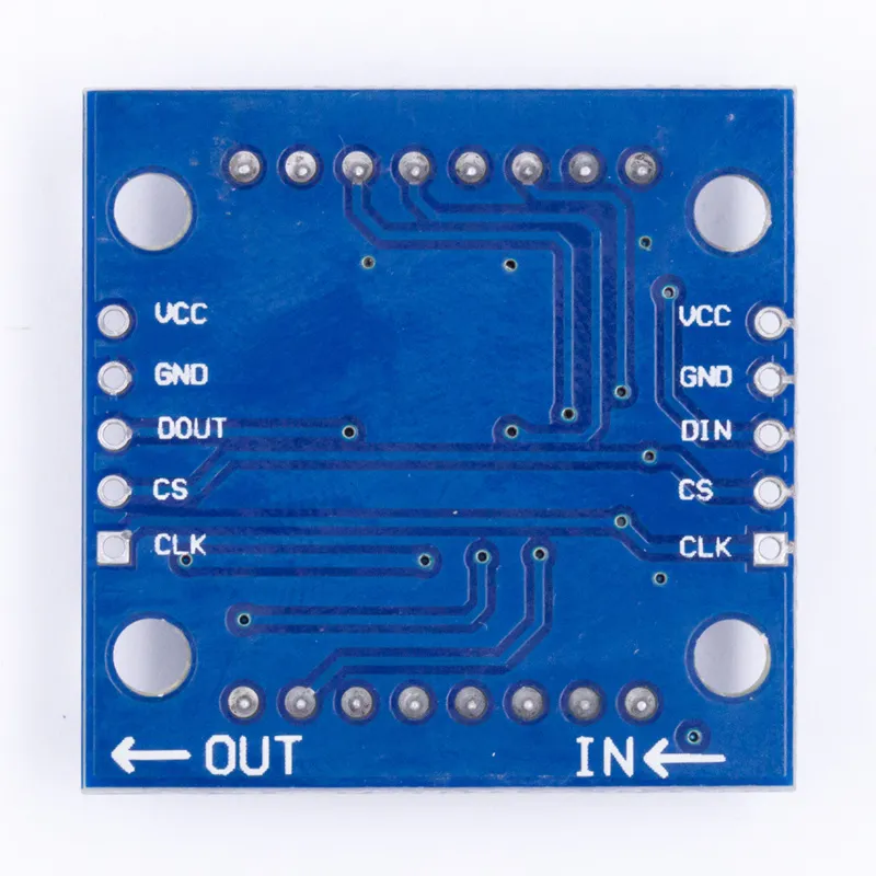
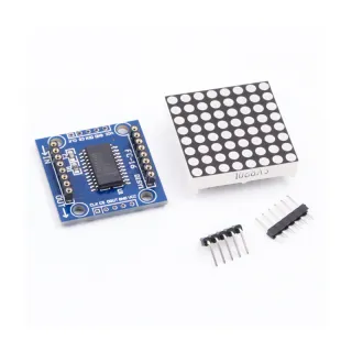
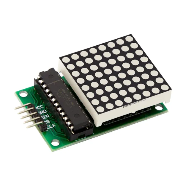
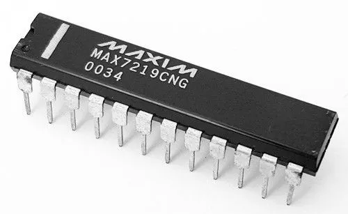
MAX7219 is een IC die wordt gebruikt voor het aansturen van LED-panelen met gemeenschappelijke kathode, displays met 7 segmenten en niveau-indicatoren die communiceren via de SPI-interface. Dit bord heeft een 8x8 dot matrix LED-display. Meerdere modules kunnen worden gecascadeerd met behulp van header-verbindingen.
Specificaties:

| Afmetingen | 3,2 cm x 3,2 cm x 1,3 cm |
|---|---|
| Bedrijfsspanning | 5V |
| Compatibiliteit | Compatibel met Arduino UNO R3 / Arduino Mega2560 |
| Driver IC | MAX7219 |
| Interface logica spanning | 5V |
| Interface type | SPI |
| Verbindingen | VCC, GND, DIN, CS, CLK |
| Bibliotheken voor Arduino | Max72xxPanel en Adafruit_GFX |
| LED-kleur | rood |
| LED-maat | 5 mm |
| Aantal cascadeerbare knooppunten | 32 (MAX) |
| Bevestigingsgaten | 4 x 3 mm |
| Werkstroom | 250mA (MAX) |
Prima product.
Niet tevreden? Je hebt 30 dagen bedenktijd na ontvangst om het product terug te sturen.
Alles over retourneren
LED Matrix Module MAX7219 Rood