Ordered on weekdays before 14:00 = shipped the same day and delivered the next day in 98% of cases. Free returns 30-day reflection period 1-year warranty

Wiring diagram and code example

How to connect the AD9850 DDS Signal Generator Module to an Arduino UNO or ESP32, with an example sketch you can upload straight away.

AD9850 DDS Sine & Square Wave Generator

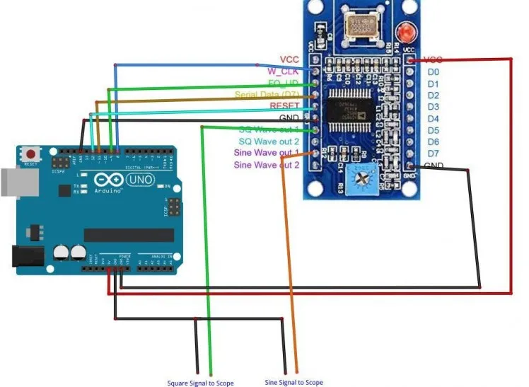
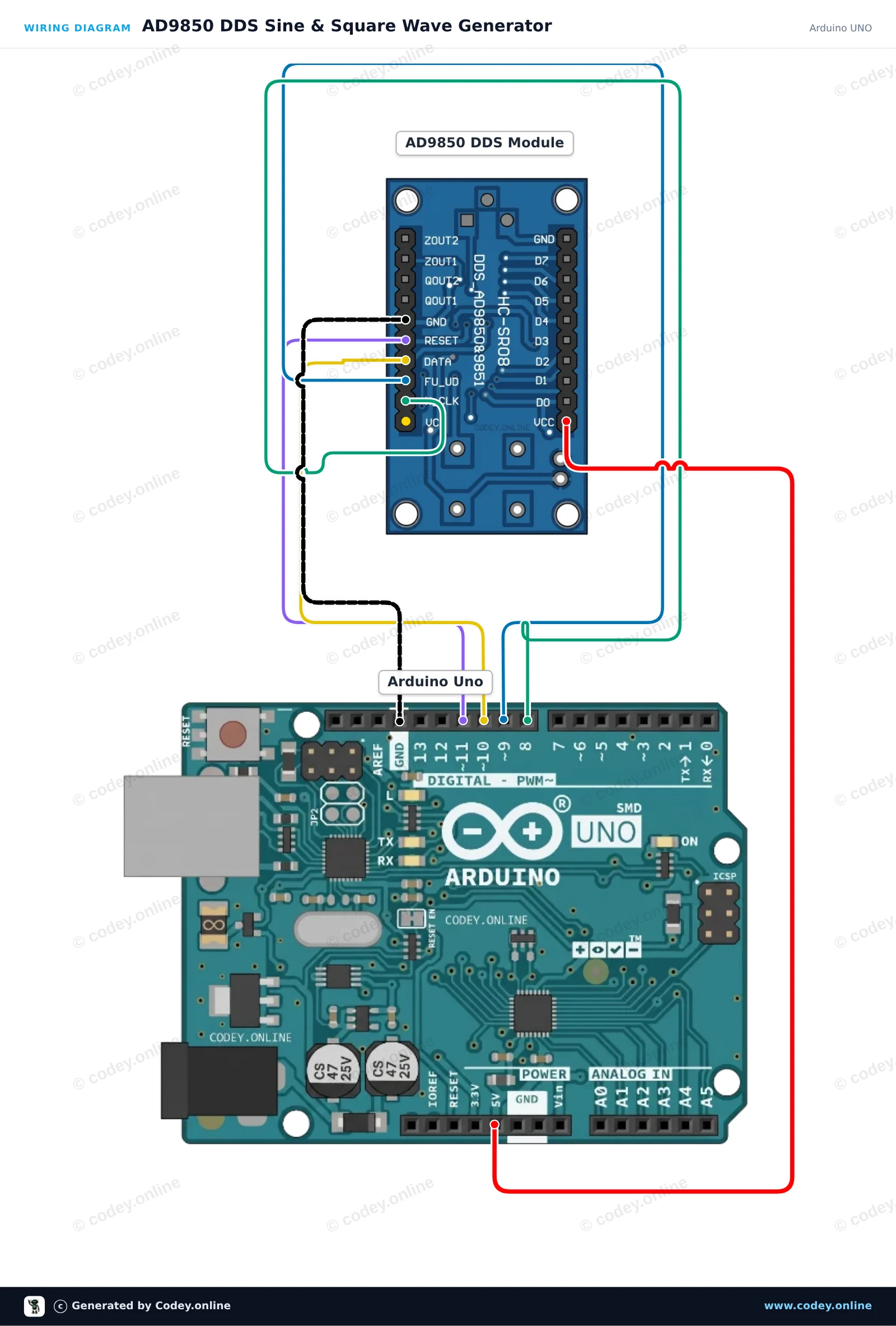
This project controls an AD9850 DDS module via a 4-wire serial interface to generate precise sine and square wave frequencies. The Arduino initializes the DDS module and periodically switches the output frequency between 1 kHz, 10 kHz, and 100 kHz. Connect an oscilloscope or frequency counter to ZOUT1 (sine wave) or QOUT1 (square wave) to inspect the output signal.

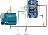
Wiring diagram: AD9850 DDS Signal Generator Module on an Arduino UNO
Wiring diagram · Click to enlarge
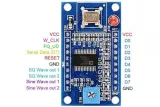
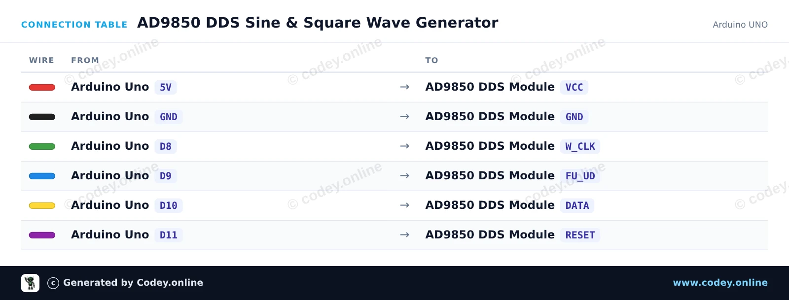
Connection table: AD9850 DDS Signal Generator Module on an Arduino UNO
Connection table · Click to enlarge
AD9850_DDS_Sine_Square_Wave_Generator.ino · compiled and verified
/*
 * ==================================================================
 *  Generated by Codey.online  —  https://www.codey.online
 * ==================================================================
 *  Project   : AD9850 DDS Sine & Square Wave Generator
 *  Board     : Arduino UNO (arduino:avr:uno)
 *  Parts     : AD9850 DDS Signal Generator Module
 *  Libraries : none (built-in)
 *
 *  Codey Online is an AI-powered browser IDE for Arduino and ESP32.
 *  Describe your project and Codey writes the code, draws the wiring
 *  diagram and uploads it to your board, straight from the browser.
 *  This code is free to use, modify and share, without warranty.
 * ==================================================================
 */

const int PIN_W_CLK = 8;
const int PIN_FQ_UD = 9;   // Labeled FU_UD on module
const int PIN_DATA  = 10;
const int PIN_RESET = 11;

const unsigned long AD9850_REF_CLOCK = 125000000UL; // 125 MHz reference oscillator

void pulsePin(int pin) {
  digitalWrite(pin, HIGH);
  delayMicroseconds(1);
  digitalWrite(pin, LOW);
  delayMicroseconds(1);
}

void ad9850Reset() {
  digitalWrite(PIN_RESET, HIGH);
  delayMicroseconds(1);
  digitalWrite(PIN_RESET, LOW);
  delayMicroseconds(1);
  pulsePin(PIN_W_CLK);
  pulsePin(PIN_FQ_UD);
}

void ad9850SetFrequency(double freqHz) {
  // Calculate 32-bit tuning word: (freq * 2^32) / ReferenceClock
  uint32_t tuningWord = (uint32_t)((freqHz * 4294967296.0) / (double)AD9850_REF_CLOCK);

  // Transmit 32-bit frequency tuning word (LSB first)
  for (int i = 0; i < 32; i++) {
    digitalWrite(PIN_DATA, (tuningWord >> i) & 0x01);
    pulsePin(PIN_W_CLK);
  }

  // Transmit 8 control/phase bits (all 0 for normal operation)
  for (int i = 0; i < 8; i++) {
    digitalWrite(PIN_DATA, LOW);
    pulsePin(PIN_W_CLK);
  }

  // Latch the updated frequency into the DDS core
  pulsePin(PIN_FQ_UD);
}

void setup() {
  pinMode(PIN_W_CLK, OUTPUT);
  pinMode(PIN_FQ_UD, OUTPUT);
  pinMode(PIN_DATA, OUTPUT);
  pinMode(PIN_RESET, OUTPUT);

  digitalWrite(PIN_W_CLK, LOW);
  digitalWrite(PIN_FQ_UD, LOW);
  digitalWrite(PIN_DATA, LOW);
  digitalWrite(PIN_RESET, LOW);

  Serial.begin(115200);
  while (!Serial) {
    ;
  }

  Serial.println(F("AD9850 DDS Generator Initialized"));
  ad9850Reset();
}

void loop() {
  const double testFrequencies[] = {1000.0, 10000.0, 100000.0};

  for (int i = 0; i < 3; i++) {
    double freq = testFrequencies[i];
    ad9850SetFrequency(freq);
    Serial.print(F("Output frequency set to: "));
    Serial.print(freq);
    Serial.println(F(" Hz"));
    delay(3000);
  }
}

Wiring diagram and example code generated by Codey.online — https://www.codey.online

AD9850 DDS Signal Generator with ESP32

This project generates precise sine and square wave signals using the AD9850 DDS module controlled by an ESP32. The sketch steps through a sequence of frequencies (1 kHz, 10 kHz, 100 kHz, and 1 MHz) every 3 seconds. Connect an oscilloscope or frequency counter to ZOUT1 for a sine wave or QOUT1 for a square wave output.

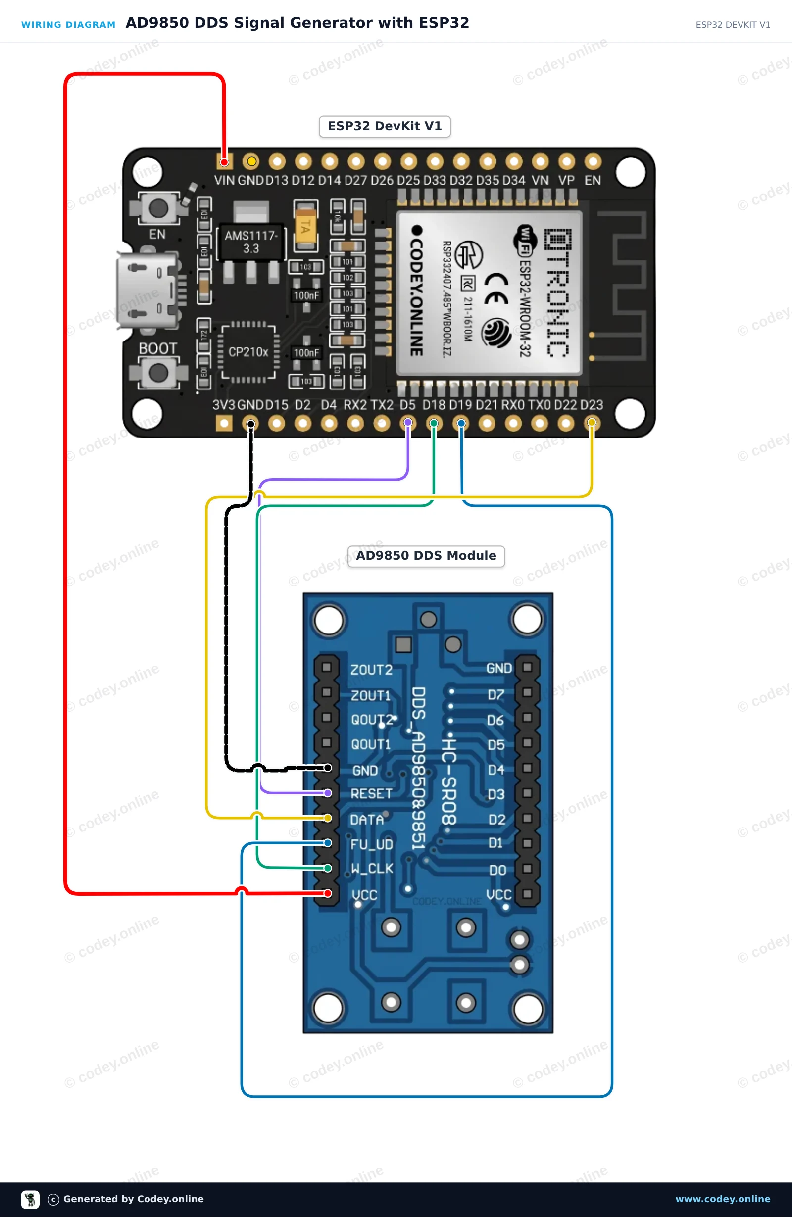
Wiring diagram: AD9850 DDS Signal Generator Module on an ESP32 DevKit V1
Wiring diagram · Click to enlarge
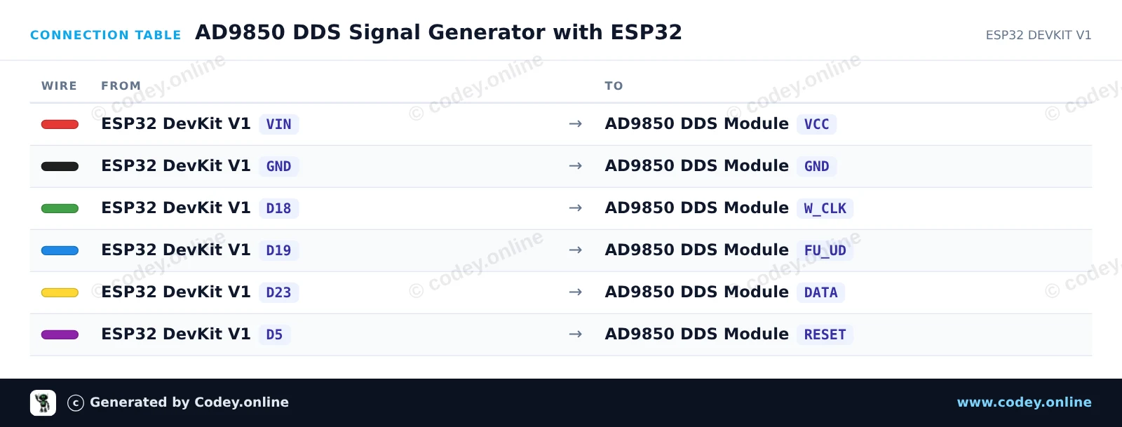
Connection table: AD9850 DDS Signal Generator Module on an ESP32 DevKit V1
Connection table · Click to enlarge
AD9850_DDS_Signal_Generator_with_ESP32.ino · compiled and verified
/*
 * ==================================================================
 *  Generated by Codey.online  —  https://www.codey.online
 * ==================================================================
 *  Project   : AD9850 DDS Signal Generator with ESP32
 *  Board     : ESP32 DEVKIT V1 (esp32:esp32:esp32doit-devkit-v1)
 *  Parts     : AD9850 DDS Signal Generator Module
 *  Libraries : none (built-in)
 *
 *  Codey Online is an AI-powered browser IDE for Arduino and ESP32.
 *  Describe your project and Codey writes the code, draws the wiring
 *  diagram and uploads it to your board, straight from the browser.
 *  This code is free to use, modify and share, without warranty.
 * ==================================================================
 */

// AD9850 DDS Signal Generator Demo on ESP32
const int W_CLK_PIN = 18;
const int FU_UD_PIN = 19;
const int DATA_PIN  = 23;
const int RESET_PIN = 5;

// 125 MHz reference clock crystal on board
const double REF_CLK = 125000000.0;

const double testFrequencies[] = {1000.0, 10000.0, 100000.0, 1000000.0};
const int numFrequencies = sizeof(testFrequencies) / sizeof(testFrequencies[0]);
int currentFreqIndex = 0;

void pulseHigh(int pin) {
  digitalWrite(pin, HIGH);
  delayMicroseconds(1);
  digitalWrite(pin, LOW);
  delayMicroseconds(1);
}

void resetAD9850() {
  pulseHigh(RESET_PIN);
  pulseHigh(W_CLK_PIN);
  pulseHigh(FU_UD_PIN); // Enable serial load mode
}

void sendFrequency(double frequency) {
  uint32_t tuningWord = (uint32_t)((frequency * 4294967296.0) / REF_CLK);

  // Send 32-bit frequency tuning word (LSB first)
  for (int i = 0; i < 32; i++) {
    digitalWrite(DATA_PIN, (tuningWord >> i) & 0x01);
    pulseHigh(W_CLK_PIN);
  }

  // Send 8 control/phase bits (0x00 for 0 phase offset)
  for (int i = 0; i < 8; i++) {
    digitalWrite(DATA_PIN, LOW);
    pulseHigh(W_CLK_PIN);
  }

  // Latch new frequency to output
  pulseHigh(FU_UD_PIN);
}

void setup() {
  Serial.begin(115200);
  delay(500);
  Serial.println("AD9850 DDS Signal Generator Initializing...");

  pinMode(W_CLK_PIN, OUTPUT);
  pinMode(FU_UD_PIN, OUTPUT);
  pinMode(DATA_PIN,  OUTPUT);
  pinMode(RESET_PIN, OUTPUT);

  digitalWrite(W_CLK_PIN, LOW);
  digitalWrite(FU_UD_PIN, LOW);
  digitalWrite(DATA_PIN,  LOW);
  digitalWrite(RESET_PIN, LOW);

  resetAD9850();
  Serial.println("AD9850 ready!");
}

void loop() {
  double freq = testFrequencies[currentFreqIndex];
  sendFrequency(freq);

  Serial.print("Output frequency set to: ");
  Serial.print(freq, 0);
  Serial.println(" Hz");

  currentFreqIndex = (currentFreqIndex + 1) % numFrequencies;
  delay(3000);
}

Wiring diagram and example code generated by Codey.online — https://www.codey.online

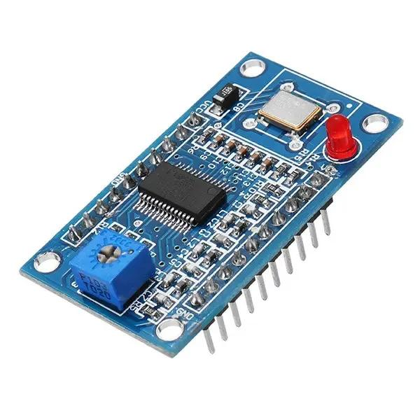
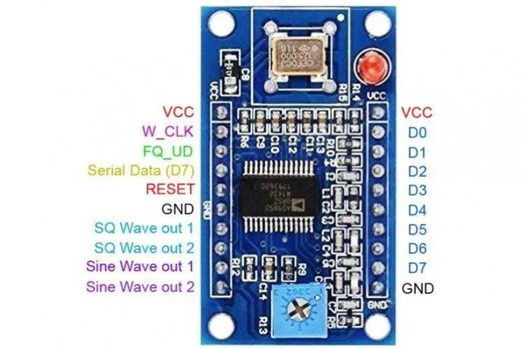
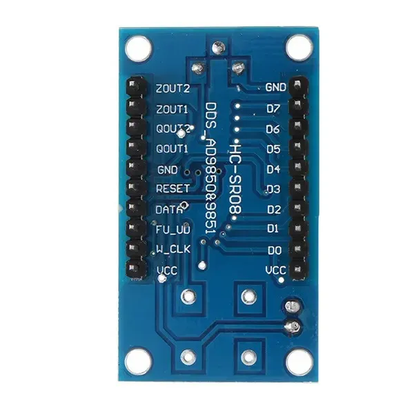
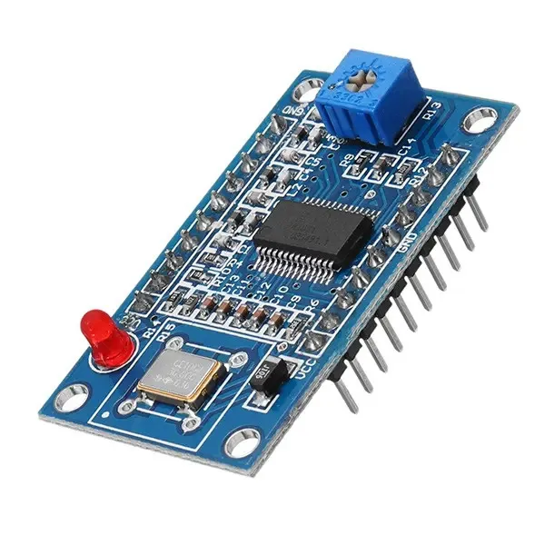
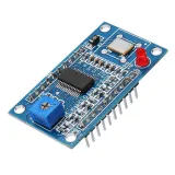
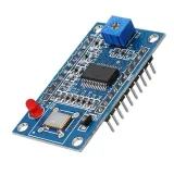
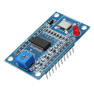
AD9850 DDS Signal Generator Module

Signal generators / Function generators are super handy from RF to embedded logic, but they are usually not very cheap.

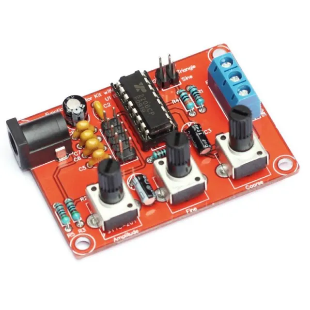
Good news: with this AD9850 DDS Module, you can create your own flexible, functional, and user-friendly Arduino frequency generator with some assembly!

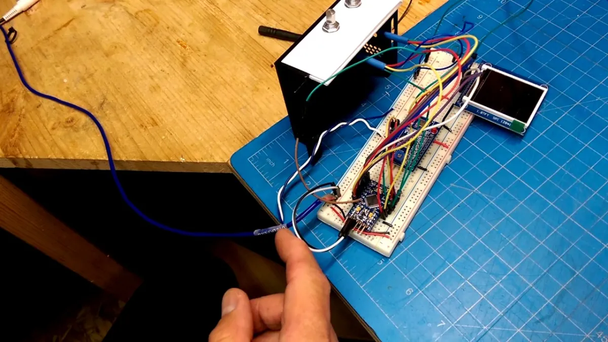
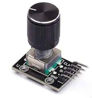
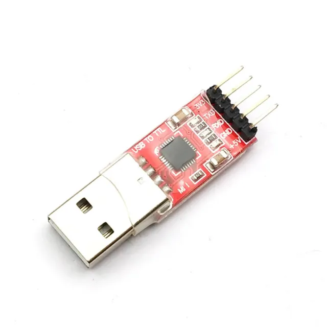
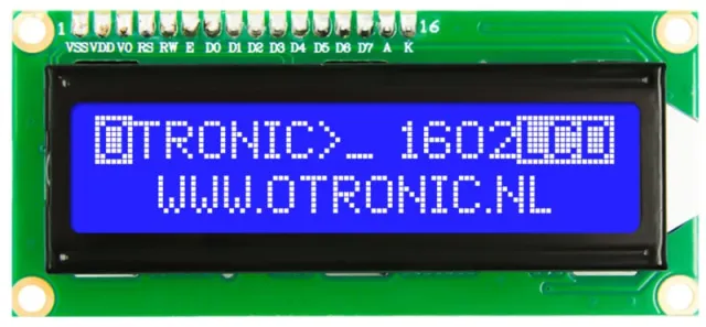
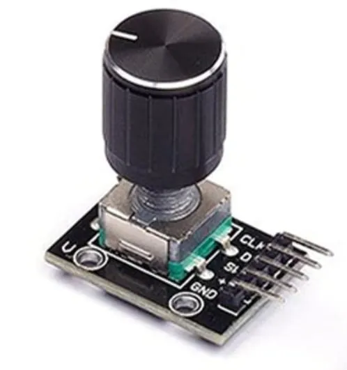
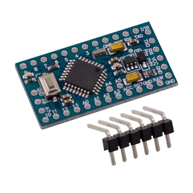
With an LED display, rotary potentiometer, and an Arduino you can make an easy-to-use, standalone signal generator. (Don't forget to purchase a CP2102 USB to TTL Serial Converter if you don't already have one at home)

You can also choose to combine it only with an Arduino Uno on a breadboard.

A completely different route is to use this module to make your own Software Defined Radio (SDR).

In short, a great module to get started with!

Features:

  • 125 MHz clock speed
  • On-Chip High Performance DAC and high speed Comparator
  • DAC SFDR > 50 dB @ 40 MHz AOUT
  • 32-bit frequency tuning word
  • Simplified control interface: parallel byte or serial load format
  • Capability for phase modulation
  • Operates with a single 3.3 V or 5 V power supply
  • Low power: 380 mW @ 125 MHz (5 V); 155 mW @ 110 MHz (3.3 V)
  • Power-down function
  • Ultra-small SSOP package with 28 leads

APPLICATIONS:

  • Frequency/phase—Agile sine wave synthesis
  • Clock recovery and locking circuits for digital communication
  • Digitally controlled ADC encoding generator
  • Agile Local Oscillator applications
  • AD9850 DDS
  • 3.3 V or 5 V
  • LED display
  • 125 MHz
Playing loads the video from YouTube.

Why choose this product?

  • Easy to use – Can be combined with Arduino and a breadboard.
  • Standalone generator – With display, potentiometer and Arduino.
  • Build your own SDR – Also suitable for Software Defined Radio.
  • Low power consumption – Operates at 380 mW or 155 mW.
  • Phase modulation possible – Supports phase modulation.
Specifications
Power supply3.3 V or 5 V
Clock speed125 MHz
Power380 mW @ 125 MHz (5 V); 155 mW @ 110 MHz (3.3 V)
ModelAD9850
Simplified control interfaceparallel byte or serial load format
Low power380 mW @ 125 MHz (5 V); 155 mW @ 110 MHz (3.3 V)
Number of outputs28

Frequently bought together

Total: € 20,90

Reviews

★★★★★ 5,0/5 1 review
  • ★★★★★Aad StekelenburgVerified purchase

    Excellent

Write a review
Your rating

Shipping & returns

Shipping

  • Parcel with track & trace€ 7,70Within 24 hours
  • Pick up at PostNL location€ 7,40Within 24 hours
  • Letterbox parcel€ 3,70Within 2 business days
  • Letterbox parcel 24 hours€ 4,55Within 24 hours
  • Pick up in storeFree
All about shipping

Returns

Not satisfied? You have 30 days after delivery to return the product.

All about returns