
Ship to all EU countries
Art: OT3345EAN: 8721244302812
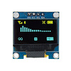
ESP32-C3 development board with 0.42 inch OLED display and WiFi/Bluetooth (OT3345)
Show all:
ESP32


Would you like to order large quantities of this product or do you need a quote to order within your organization? Then request a quote.
REQUEST QUOTEThank you for your request.
You will receive the quote in your mailbox within a few minutes.
You will receive the quote in your mailbox within a few minutes.
Ship to all EU countries
Ordered on working days before 14:00 AM = shipped the same day.
30 days cooling-off period
1 jaar garantie
Description
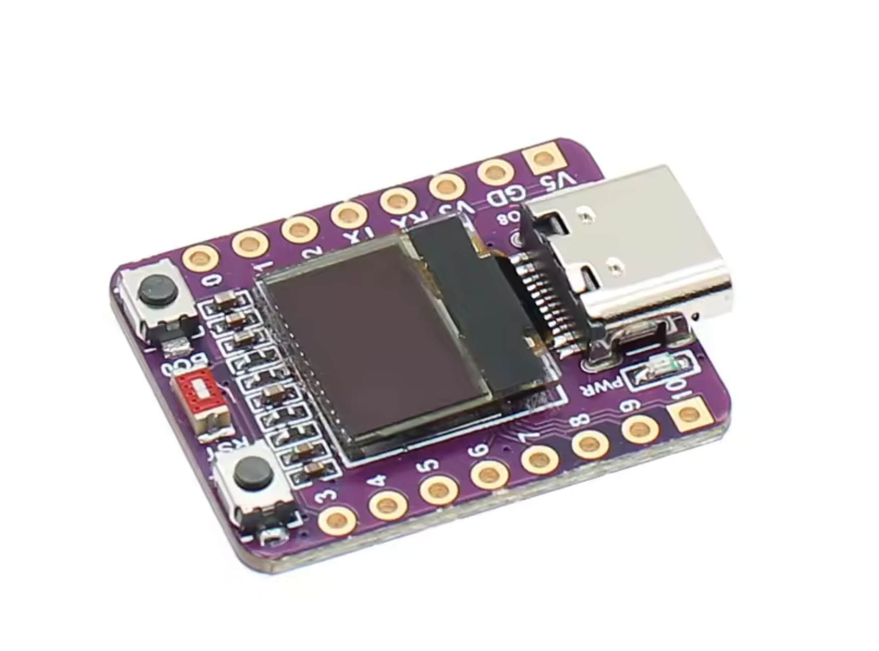
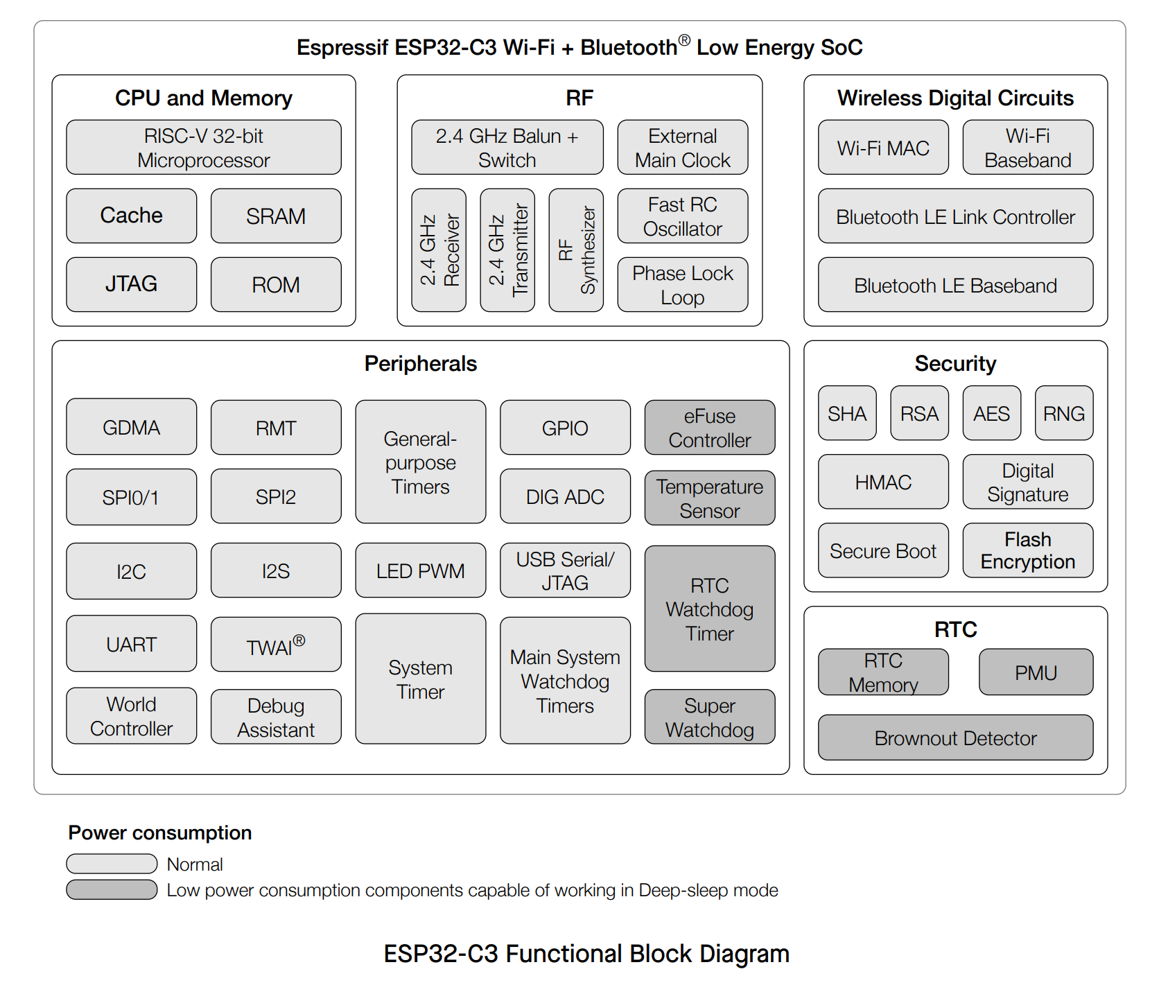
ESP32-C3 development board with mini 0.42 inch OLED display
This ESP32-C3 development board combines wireless connectivity with a compact 0.42 inch OLED display. The board is based on the reliable ESP32C3FN4/FH4 chip and features a built-in ceramic antenna for WiFi and Bluetooth. With 4MB flash memory and USB programming, it is ideal for various IoT projects.
Main features
- Processor: ESP32-C3FN4/FH4, 32-bit RISC-V single-core up to 160 MHz
- Flash memory: 4MB
- Display: 0.42-inch OLED for direct visual feedback
- Connectivity: Dual-mode WiFi (802.11b/g/n) and Bluetooth 5 (LE, mesh)
- Programming: Easy via USB
- Antenna: Built-in ceramic antenna
WiFi and Bluetooth features
- WiFi with data rates up to 150 Mbps, support for 20/40 MHz bandwidth
- Support for multiple WiFi modes: Station, SoftAP, and promiscuous mode
- Bluetooth 5 LE with high transmit power up to 20 dBm and mesh networking
- Internal coexistence between WiFi and Bluetooth for shared antenna use
Hardware and interfaces
- 22 programmable GPIO pins
- Communication via UART, SPI, I2C, I2S, and USB Serial/JTAG
- Analog functions: two 12-bit SAR ADCs, temperature sensor
- Timers and watchdogs for reliable timing and fault detection
Low power consumption and security
- Four power-saving modes, including deep-sleep with only 5 µA current consumption
- Security features such as secure boot and flash encryption
- Cryptographic hardware acceleration: AES, SHA, RSA, and more
Applications
Due to its low power consumption and versatile connectivity, this board is suitable for:
- Smart Home devices
- Industrial automation
- Healthcare
- Consumer electronics
- Smart Agriculture
- POS systems
- Service robots
- Audio equipment
- Low-power IoT sensors and data loggers
Product Manual: ESP32-C3 Development Board with 0.42" OLED
This compact IoT board is based on the ESP32-C3 (RISC-V) chip and features an integrated 0.42-inch OLED display. Since the pinout and display driver differ from standard ESP32 modules, please use the specific instructions below to operate the board correctly.
1. Key Hardware Specifications
- Chip: ESP32-C3FN4 (4MB Flash, WiFi & Bluetooth 5.0).
- USB: Native USB (USB-C). Note: Enable "USB CDC On Boot" in Arduino IDE for Serial Monitor support.
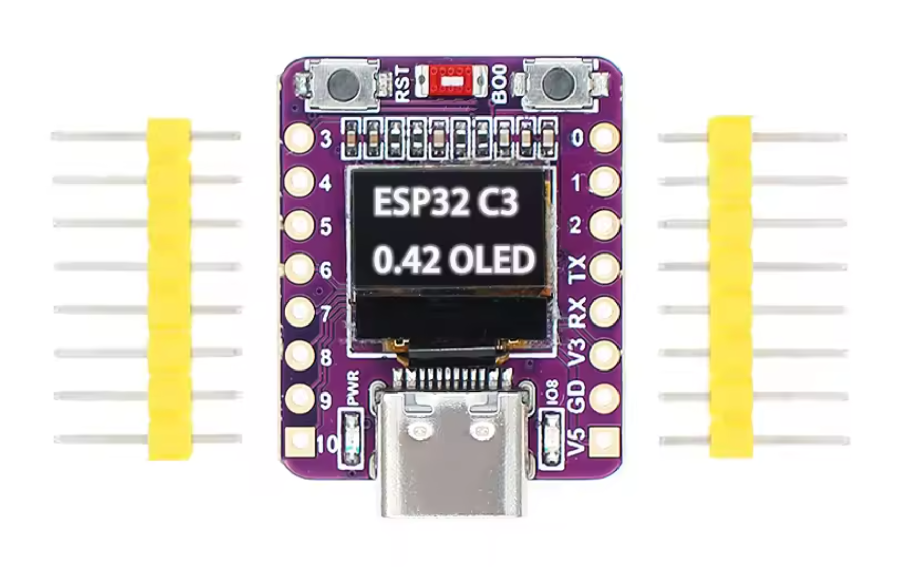
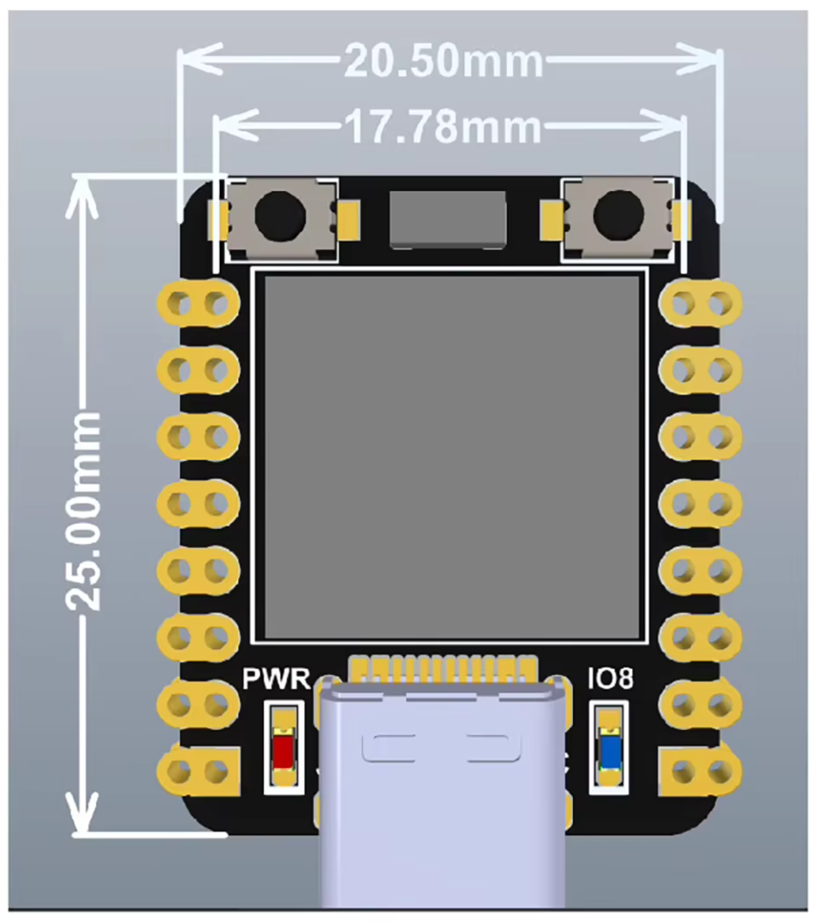
- OLED Display: 0.42 inch (effective resolution 72x40 pixels).
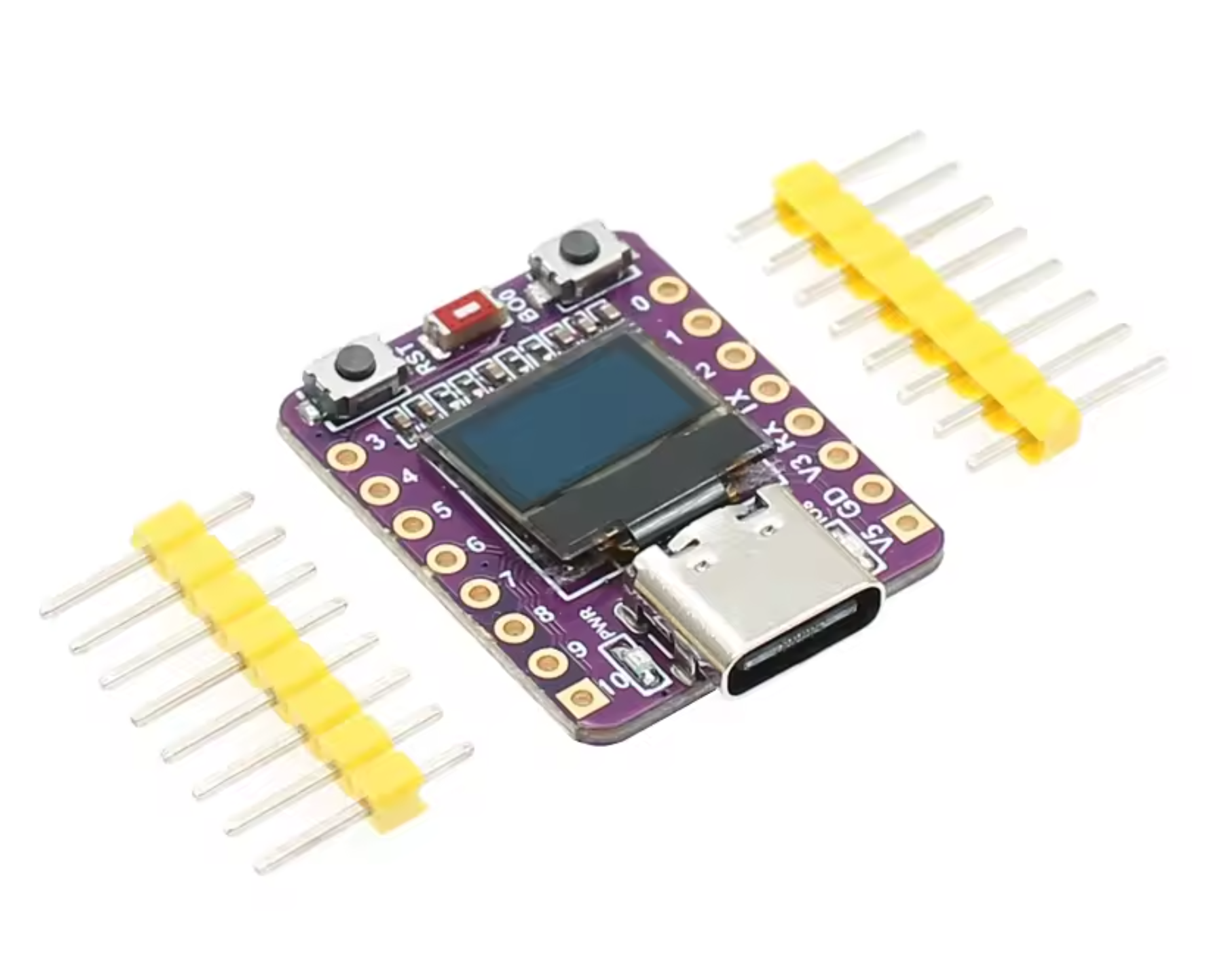
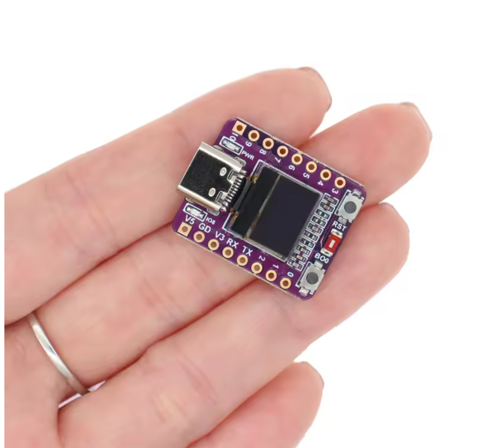
- Dimensions: Very compact (approx. 20x25mm).
2. Pinout & Connections (Important!)
Online documentation is often confusing. Please use the pin assignments below for this specific board (ABRobot style):
- OLED I2C SDA: GPIO 5 (Not 8, as often stated in schematics).
- OLED I2C SCL: GPIO 6 (Not 9).
- Onboard LED: GPIO 8 (Active LOW:
LOW= on,HIGH= off). - Boot Button: GPIO 9.
- Hardware Serial (UART0): TX = GPIO 21, RX = GPIO 20.
3. Arduino IDE Settings
To program this board, select the following settings in the Arduino IDE:
- Board:
ESP32C3 Dev Module - USB CDC On Boot:
Enabled(Essential to see Serial.print output). - Flash Mode:
DIO(default).
Tip for the first upload:
If the upload fails, hold the BOOT button, press RESET shortly, and then release BOOT. This forces the board into download mode.
If the upload fails, hold the BOOT button, press RESET shortly, and then release BOOT. This forces the board into download mode.
4. Driving the OLED Display (Crucial)
The screen uses an SSD1306 controller but has a physical resolution of only 72x40 pixels. However, the internal buffer is 128x64. You must apply an "offset" to make text visible.
Required Library: Install the U8g2 library (by olikraus) via the Arduino Library Manager.
Example Code:
#include <U8g2lib.h>
#include <Wire.h>

// Initialization for ESP32-C3 with I2C on pin 5 (SDA) and 6 (SCL)
// We use the standard 128x64 driver but only a portion of the screen.
U8G2_SSD1306_128X64_NONAME_F_HW_I2C u8g2(U8G2_R0, U8X8_PIN_NONE, 6, 5);

// Settings for the 0.42 inch display
int width = 72;
int height = 40;

// Offsets are required to center the output within the 128x64 buffer
int xOffset = 30; // 30 works best in practice
int yOffset = 12; // (64 - 40) / 2 = 12

void setup(void) {
  delay(1000); // Short pause for stability

  u8g2.begin();
  u8g2.setContrast(255);      // Max brightness
  u8g2.setBusClock(400000);   // 400kHz I2C speed
  u8g2.setFont(u8g2_font_ncenB10_tr); // Choose a readable font
}

void loop(void) {
  u8g2.clearBuffer(); // Clear internal buffer

  // Draw a frame to test the visible area
  u8g2.drawFrame(xOffset, yOffset, width, height);

  // Draw text (account for xOffset and yOffset!)
  u8g2.setCursor(xOffset + 5, yOffset + 25);
  u8g2.print("ESP32-C3");

  u8g2.sendBuffer(); // Send data to display
  delay(1000);
}
5. Checking Extra Pins (LED Blink)
Want to test the other pins? Use this simple loop. Note: pin 8 also controls the onboard LED.
// GPIO 8 is the Onboard LED (LOW = ON)
#define LED_PIN 8

void setup() {
  pinMode(LED_PIN, OUTPUT);
}

void loop() {
  digitalWrite(LED_PIN, LOW);  // LED On
  delay(500);
  digitalWrite(LED_PIN, HIGH); // LED Off
  delay(500);
}
Reviews
Add your review
9.6/10
jk kaptijn
Staat al een programmatje op die gelijk met WiFi verbinding maakt met je telefoon
Posted on 08/07/2026Joop Boerma
Werkt zoals verwacht!!
Posted on 19/02/2026Michel Gutlich
Goed verpakt in klein opbergdoosje en in prima staat
Posted on 02/02/2026Dirk Kop
leuk product
Posted on 02/02/2026Yrrah
Goede intro in de ESP32 wereld
Posted on 02/02/2026Also interesting for you:


Previously viewed


Kies je taal / Choose your language: