Ordered on weekdays before 14:00 = shipped the same day and delivered the next day in 98% of cases. Free returns 30-day reflection period 1-year warranty

Wiring diagram and code example

How to connect the MAX485 TTL to RS485 Converter Module to an Arduino UNO or ESP32, with an example sketch you can upload straight away.

MAX485 RS-485 Transceiver Communication

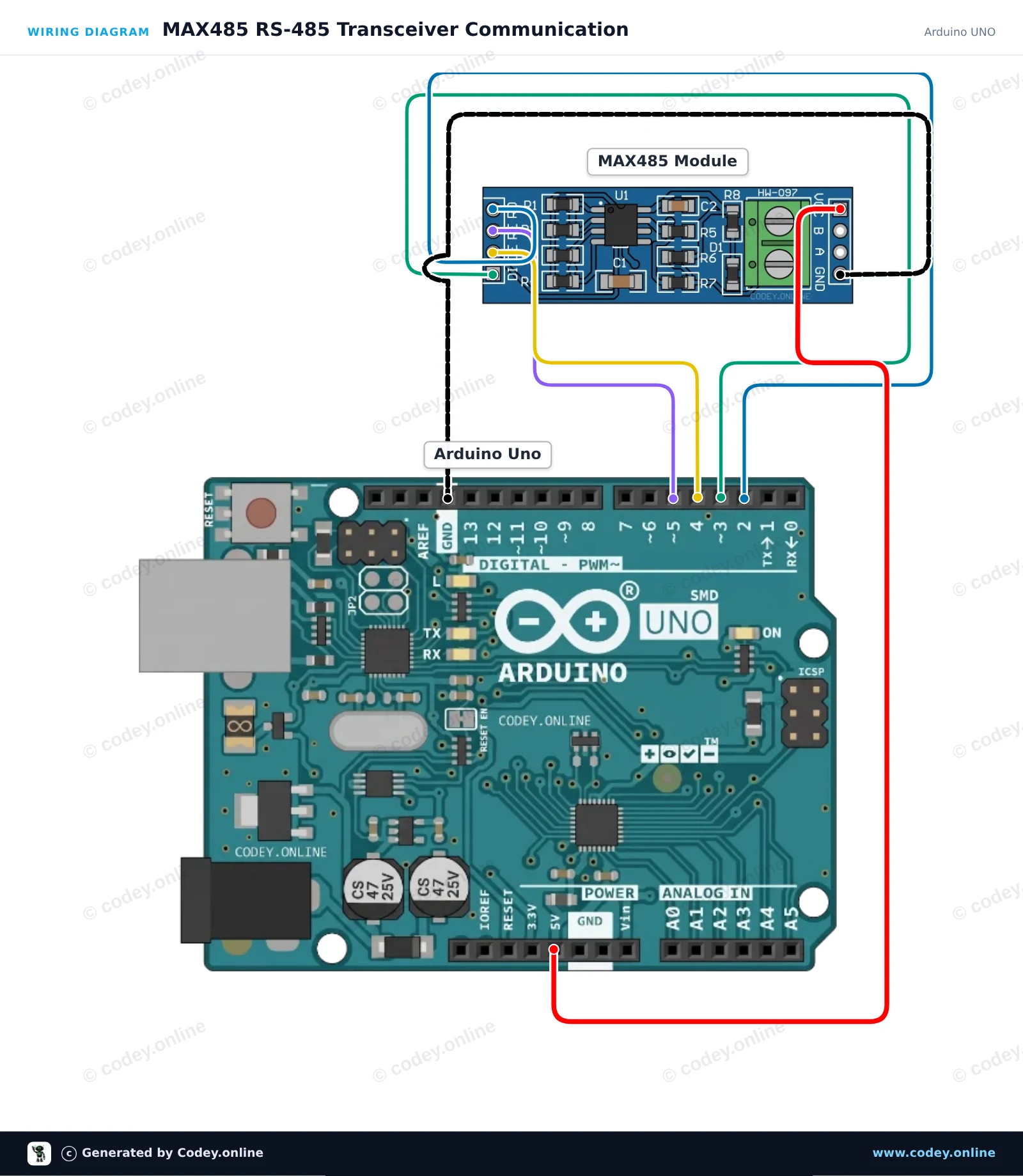
This circuit interfaces an Arduino Uno with an RS-485 differential bus using the MAX485 transceiver. SoftwareSerial handles communication with the module, while digital pins control transmit and receive modes. Any message typed into the Serial Monitor is transmitted over RS-485, and incoming bus data is printed to the screen.

Wiring diagram: MAX485 TTL to RS485 Converter Module on an Arduino UNO
Wiring diagram · Click to enlarge
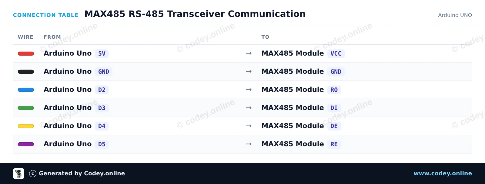
Connection table: MAX485 TTL to RS485 Converter Module on an Arduino UNO
Connection table · Click to enlarge
MAX485_RS_485_Transceiver_Communication.ino · compiled and verified
/*
 * ==================================================================
 *  Generated by Codey.online  —  https://www.codey.online
 * ==================================================================
 *  Project   : MAX485 RS-485 Transceiver Communication
 *  Board     : Arduino UNO (arduino:avr:uno)
 *  Parts     : MAX485 TTL to RS485 Converter Module
 *  Libraries : none (built-in)
 *
 *  Codey Online is an AI-powered browser IDE for Arduino and ESP32.
 *  Describe your project and Codey writes the code, draws the wiring
 *  diagram and uploads it to your board, straight from the browser.
 *  This code is free to use, modify and share, without warranty.
 * ==================================================================
 */

#include <SoftwareSerial.h>

const byte PIN_RO = 2;   // Receiver Out (RX)
const byte PIN_DI = 3;   // Driver In (TX)
const byte PIN_DE = 4;   // Driver Enable (Active HIGH)
const byte PIN_RE = 5;   // Receiver Enable (Active LOW)

SoftwareSerial rs485(PIN_RO, PIN_DI);

unsigned long lastSend = 0;
int packetCount = 0;

void setTransmitMode() {
  digitalWrite(PIN_RE, HIGH); // Disable receiver
  digitalWrite(PIN_DE, HIGH); // Enable driver
  delayMicroseconds(50);
}

void setReceiveMode() {
  digitalWrite(PIN_DE, LOW);  // Disable driver
  digitalWrite(PIN_RE, LOW);  // Enable receiver
  delayMicroseconds(50);
}

void rs485Send(const String &msg) {
  setTransmitMode();
  rs485.println(msg);
  rs485.flush();
  setReceiveMode();
}

void setup() {
  pinMode(PIN_DE, OUTPUT);
  pinMode(PIN_RE, OUTPUT);
  setReceiveMode();

  Serial.begin(115200);
  rs485.begin(9600);

  Serial.println(F("MAX485 RS-485 Transceiver Demo"));
  Serial.println(F("Type a message and press Enter to send over RS-485."));
}

void loop() {
  // Forward incoming Serial Monitor input to RS-485
  if (Serial.available()) {
    String input = Serial.readStringUntil('\n');
    input.trim();
    if (input.length() > 0) {
      Serial.print(F("Sending: "));
      Serial.println(input);
      rs485Send(input);
    }
  }

  // Forward received RS-485 data to Serial Monitor
  if (rs485.available()) {
    Serial.print(F("Received: "));
    while (rs485.available()) {
      char c = (char)rs485.read();
      Serial.print(c);
      delay(2);
    }
    Serial.println();
  }

  // Automatically send a heartbeat packet every 5 seconds
  if (millis() - lastSend >= 5000) {
    lastSend = millis();
    packetCount++;
    String packet = "Ping #" + String(packetCount);
    Serial.print(F("Auto-transmitting: "));
    Serial.println(packet);
    rs485Send(packet);
  }
}

Wiring diagram and example code generated by Codey.online — https://www.codey.online

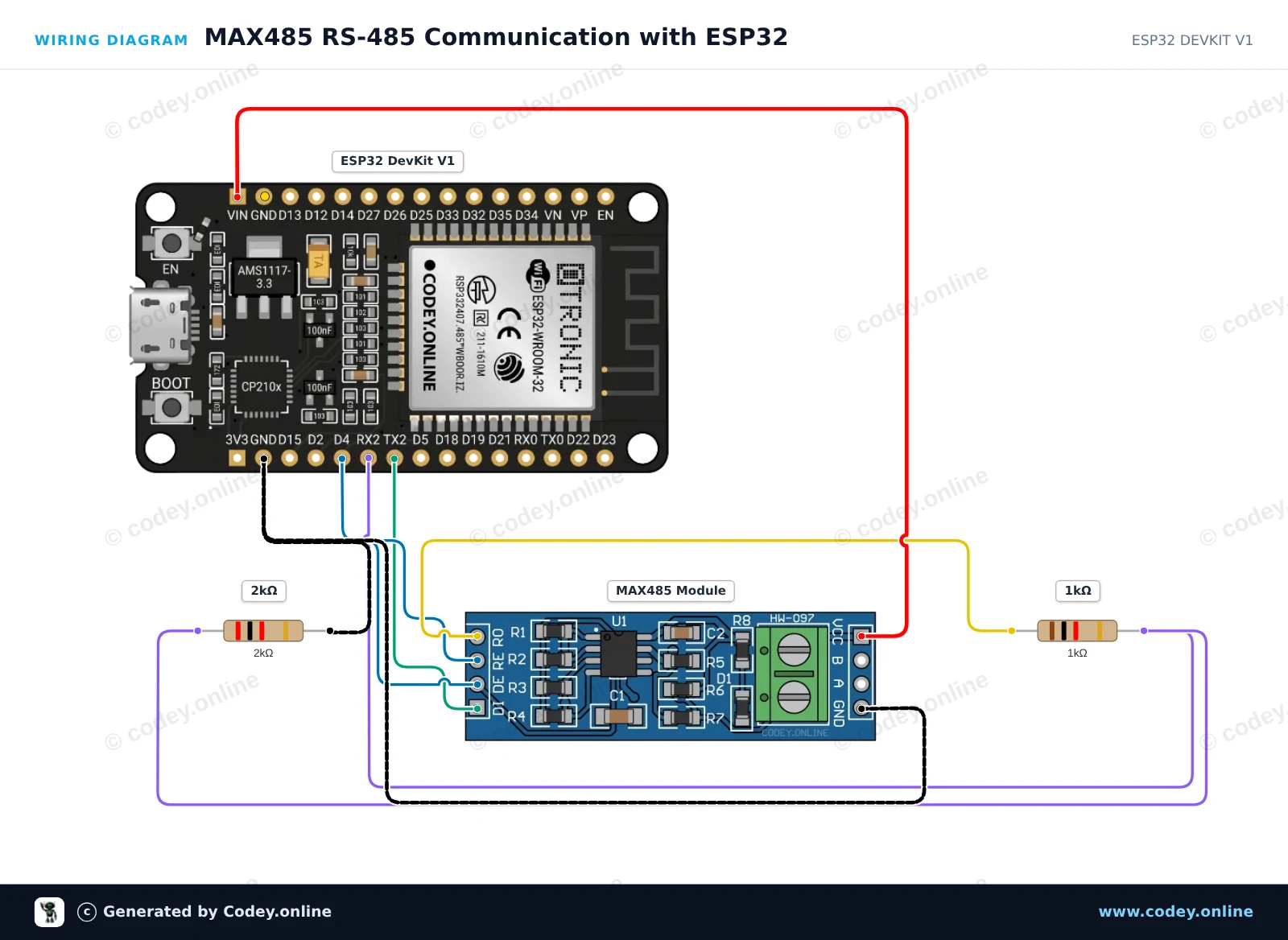
MAX485 RS-485 Communication with ESP32

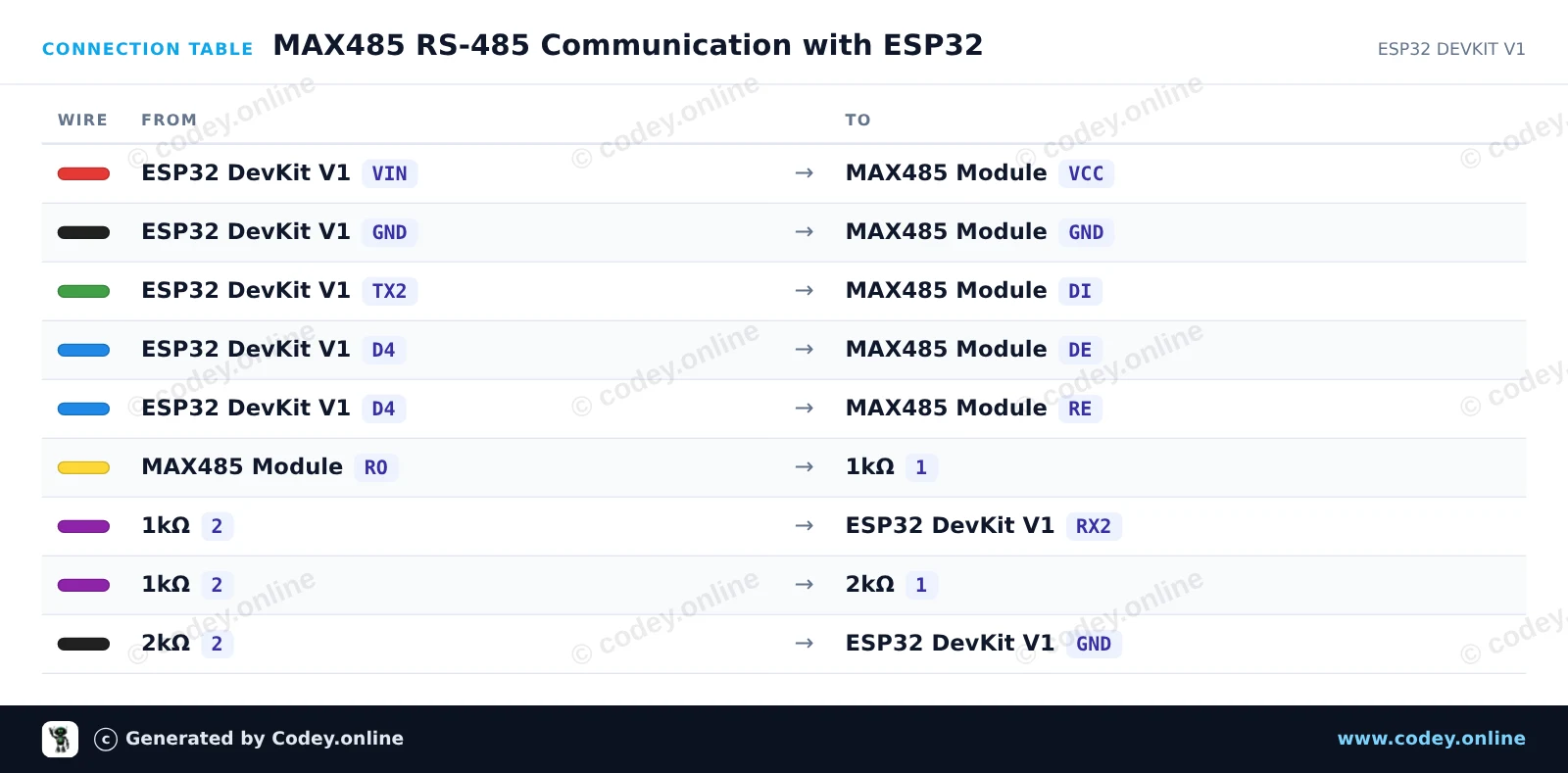
This project demonstrates sending and receiving data over an RS-485 bus using the MAX485 module and ESP32 UART2. The ESP32 switches the DE/RE pins HIGH to transmit a periodic heartbeat message and sets them LOW to listen for incoming RS-485 packets. A simple 1kΩ/2kΩ voltage divider safely drops the 5V TTL output (RO) of the module to 3.3V for the ESP32 RX pin.

Wiring diagram: MAX485 TTL to RS485 Converter Module on an ESP32 DevKit V1
Wiring diagram · Click to enlarge
Connection table: MAX485 TTL to RS485 Converter Module on an ESP32 DevKit V1
Connection table · Click to enlarge
MAX485_RS_485_Communication_with_ESP32.ino · compiled and verified
/*
 * ==================================================================
 *  Generated by Codey.online  —  https://www.codey.online
 * ==================================================================
 *  Project   : MAX485 RS-485 Communication with ESP32
 *  Board     : ESP32 DEVKIT V1 (esp32:esp32:esp32doit-devkit-v1)
 *  Parts     : MAX485 TTL to RS485 Converter Module
 *  Libraries : none (built-in)
 *
 *  Codey Online is an AI-powered browser IDE for Arduino and ESP32.
 *  Describe your project and Codey writes the code, draws the wiring
 *  diagram and uploads it to your board, straight from the browser.
 *  This code is free to use, modify and share, without warranty.
 * ==================================================================
 */

// MAX485 TTL to RS-485 transceiver demo with ESP32

const int CONTROL_PIN = 4; // Controls DE and RE (HIGH = Transmit, LOW = Receive)
const int RXD2_PIN = 16;
const int TXD2_PIN = 17;

unsigned long lastSendTime = 0;
int messageCount = 0;

void setup() {
  Serial.begin(115200);
  pinMode(CONTROL_PIN, OUTPUT);
  digitalWrite(CONTROL_PIN, LOW); // Start in receive mode

  // Initialize UART2 for RS-485 communication
  Serial2.begin(9600, SERIAL_8N1, RXD2_PIN, TXD2_PIN);

  Serial.println("RS-485 Transceiver Ready");
}

void loop() {
  // Send a message every 2 seconds
  if (millis() - lastSendTime >= 2000) {
    lastSendTime = millis();
    messageCount++;

    // Enable RS-485 transmitter
    digitalWrite(CONTROL_PIN, HIGH);
    delay(10);

    String msg = "Hello from ESP32 #" + String(messageCount);
    Serial2.println(msg);
    Serial2.flush(); // Wait until all outgoing bytes are transmitted

    // Return to receive mode
    digitalWrite(CONTROL_PIN, LOW);

    Serial.print("Sent over RS-485: ");
    Serial.println(msg);
  }

  // Check for incoming RS-485 data
  if (Serial2.available()) {
    Serial.print("Received via RS-485: ");
    while (Serial2.available()) {
      char c = (char)Serial2.read();
      Serial.print(c);
    }
    Serial.println();
  }
}

Wiring diagram and example code generated by Codey.online — https://www.codey.online

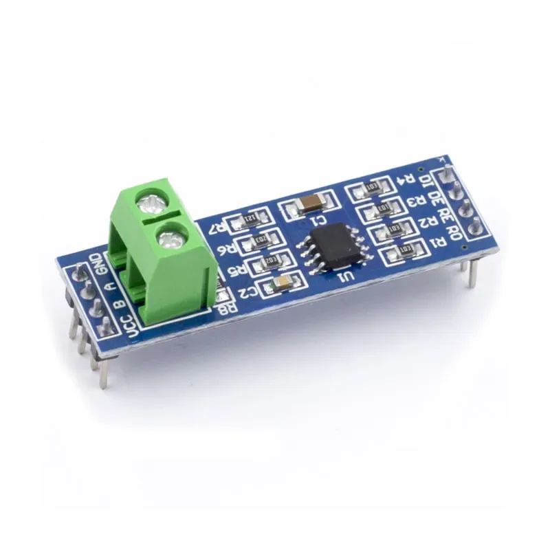
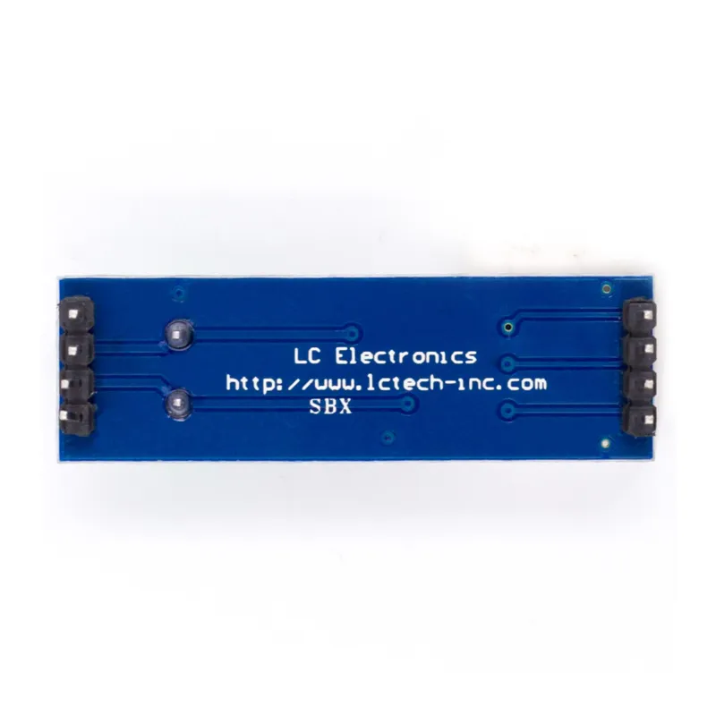
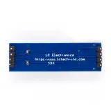
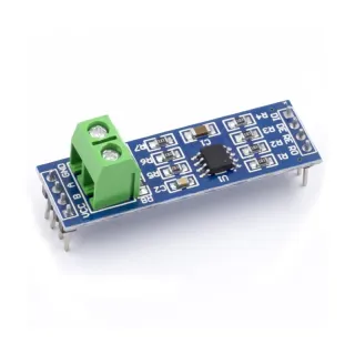
MAX485 TTL to RS485 Converter Module

MAX485 module with the MAX485 chip with low power consumption for RS-485 communication. RS485 is used for serial communication over longer distances than direct RS232 or TTL and supports multiple units on the same bus.

MAX485 module specifications:
– Works on: 5V.
– Onboard connection for RS-485 wires.
– Dimensions: 44mm x 14mm.

Dimensions
Length: 4,39cm
Width: 1,41cm
Height: 1,89cm

  • RS-485 communication
  • Low power consumption
  • Onboard connection
  • 44 x 14 mm

Why choose this product?

  • Long distance – Suitable for communication over longer distances.
  • Multiple units – Supports multiple units on the same bus.
  • Low power consumption – Has low power consumption.
  • Onboard connection – RS-485 wires are present.
Specifications
Width1,41cm
Operating voltage5V
Length4,39cm
Height1,89cm

Frequently bought together

Total: € 11,85

Reviews

★★★★★ 4,5/5 2 reviews
  • ★★★★★Gerrit NijhofVerified purchase

    I assume it works just as well as the Rs232 module. I ordered this 485 module as well so that in a while I can connect an easun hybrid inverter to an Arduino. So I haven't used it yet.

  • ★★★★★AnoniemVerified purchase

    Standard, what is there to say about it?

Write a review
Your rating

Shipping & returns

Shipping

  • Parcel with track & trace€ 7,70Within 24 hours
  • Pick up at PostNL location€ 7,40Within 24 hours
  • Letterbox parcel€ 3,70Within 2 business days
  • Letterbox parcel 24 hours€ 4,55Within 24 hours
  • Pick up in storeFree
All about shipping

Returns

Not satisfied? You have 30 days after delivery to return the product.

All about returns

Recently viewed