Ordered on weekdays before 14:00 = shipped the same day and delivered the next day in 98% of cases. Free returns 30-day reflection period 1-year warranty

Wiring diagram and code example

How to connect the PWM to Voltage converter module 0-10V to an Arduino UNO or ESP32, with an example sketch you can upload straight away.

PWM to 0-10V Voltage Converter Demo

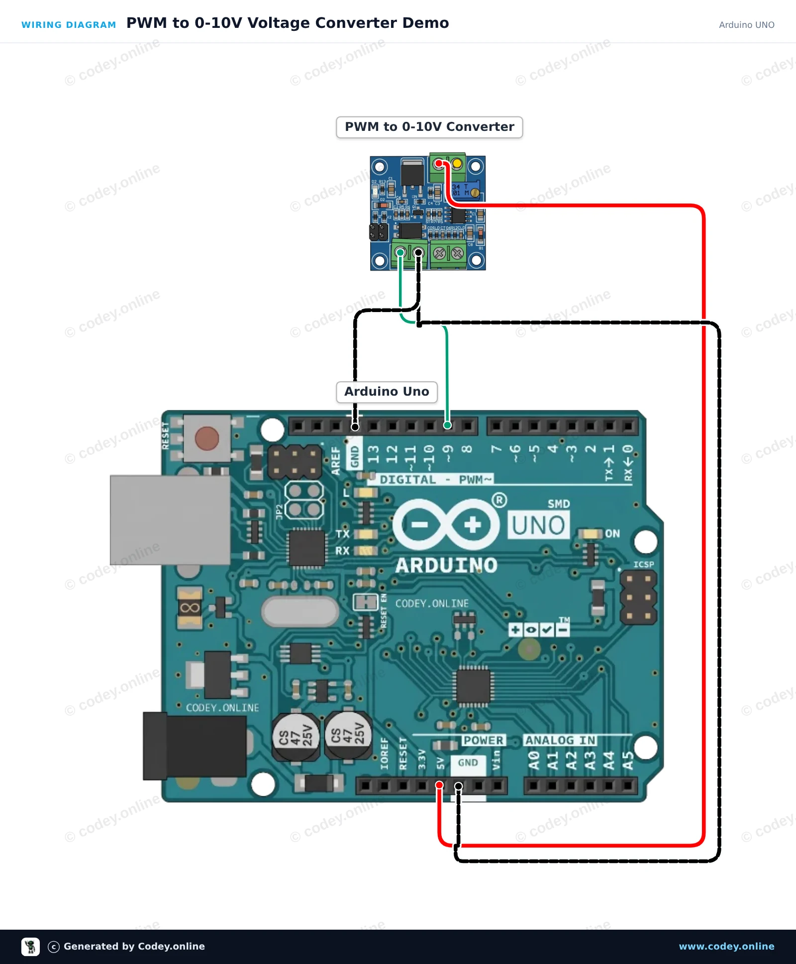
This project demonstrates how to generate an analog control voltage (0-10V) using an Arduino PWM output. The Arduino outputs a varying PWM signal on pin 9, which the module converts into a proportional DC voltage at the VOUT terminal. Open the Serial Monitor to observe the current PWM duty cycle as the output sweeps up and down.

Wiring diagram: PWM to Voltage converter module 0-10V on an Arduino UNO
Wiring diagram · Click to enlarge
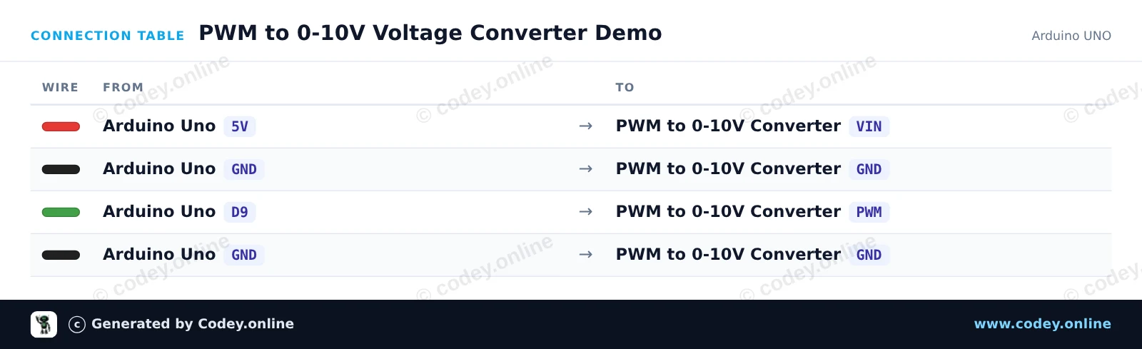
Connection table: PWM to Voltage converter module 0-10V on an Arduino UNO
Connection table · Click to enlarge
PWM_to_0_10V_Voltage_Converter_Demo.ino · compiled and verified
/*
 * ==================================================================
 *  Generated by Codey.online  —  https://www.codey.online
 * ==================================================================
 *  Project   : PWM to 0-10V Voltage Converter Demo
 *  Board     : Arduino UNO (arduino:avr:uno)
 *  Parts     : PWM naar Voltage converter module 0-10V
 *  Libraries : none (built-in)
 *
 *  Codey Online is an AI-powered browser IDE for Arduino and ESP32.
 *  Describe your project and Codey writes the code, draws the wiring
 *  diagram and uploads it to your board, straight from the browser.
 *  This code is free to use, modify and share, without warranty.
 * ==================================================================
 */

// PWM to 0-10V Voltage Converter Demo

const int pwmPin = 9;

void setup() {
  pinMode(pwmPin, OUTPUT);
  Serial.begin(115200);
  Serial.println(F("PWM to Voltage Converter initialized."));
}

void loop() {
  // Ramp up output voltage (0% to 100% duty cycle)
  Serial.println(F("Ramping voltage up..."));
  for (int duty = 0; duty <= 255; duty += 5) {
    analogWrite(pwmPin, duty);
    Serial.print(F("Duty cycle: "));
    Serial.print((duty * 100) / 255);
    Serial.println(F("%"));
    delay(50);
  }
  
  delay(1000);

  // Ramp down output voltage (100% to 0% duty cycle)
  Serial.println(F("Ramping voltage down..."));
  for (int duty = 255; duty >= 0; duty -= 5) {
    analogWrite(pwmPin, duty);
    Serial.print(F("Duty cycle: "));
    Serial.print((duty * 100) / 255);
    Serial.println(F("%"));
    delay(50);
  }
  
  delay(1000);
}

Wiring diagram and example code generated by Codey.online — https://www.codey.online

ESP32 PWM to 0-10V Voltage Converter Demo

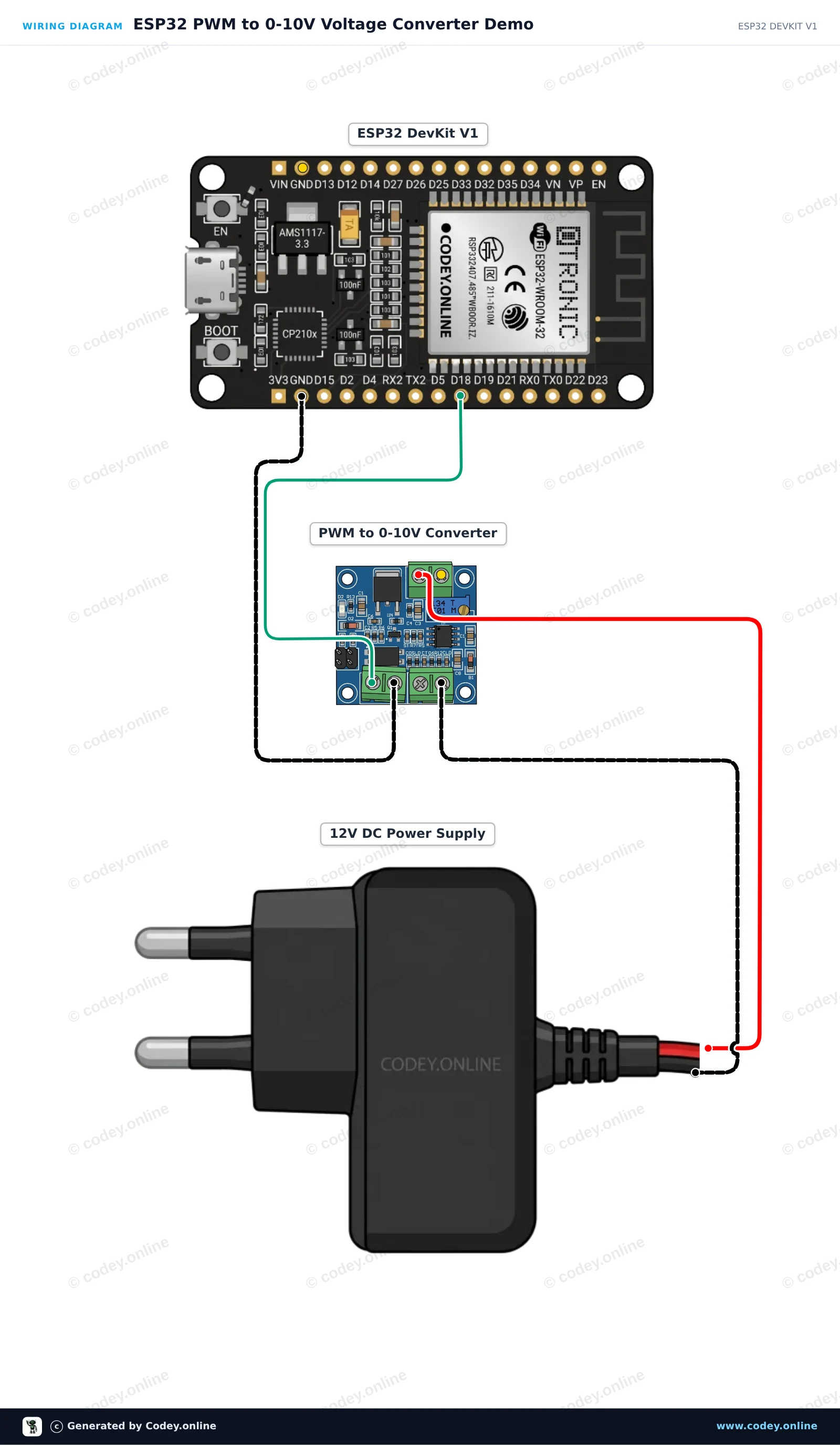
This project demonstrates converting a digital PWM signal from the ESP32 into an analog 0-10V control voltage using the PWM-to-Voltage converter module. The module is powered by an external 12V DC supply and controlled via GPIO 18. The sketch sweeps the PWM duty cycle from 0% to 100%, generating an analog output ranging from 0V to 10V (ideal for PLCs, VFDs, or industrial dimmers).

Wiring diagram: PWM to Voltage converter module 0-10V on an ESP32 DevKit V1
Wiring diagram · Click to enlarge
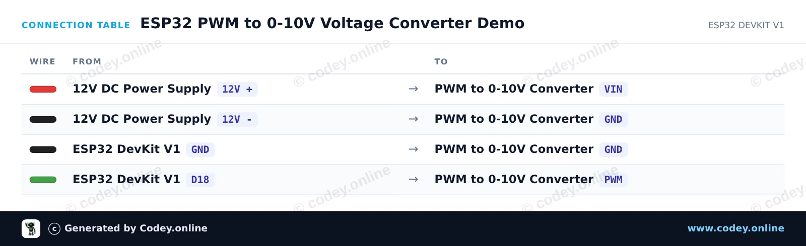
Connection table: PWM to Voltage converter module 0-10V on an ESP32 DevKit V1
Connection table · Click to enlarge
ESP32_PWM_to_0_10V_Voltage_Converter_Dem.ino · compiled and verified
/*
 * ==================================================================
 *  Generated by Codey.online  —  https://www.codey.online
 * ==================================================================
 *  Project   : ESP32 PWM to 0-10V Voltage Converter Demo
 *  Board     : ESP32 DEVKIT V1 (esp32:esp32:esp32doit-devkit-v1)
 *  Parts     : PWM naar Voltage converter module 0-10V
 *  Libraries : none (built-in)
 *
 *  Codey Online is an AI-powered browser IDE for Arduino and ESP32.
 *  Describe your project and Codey writes the code, draws the wiring
 *  diagram and uploads it to your board, straight from the browser.
 *  This code is free to use, modify and share, without warranty.
 * ==================================================================
 */

// PWM to 0-10V Converter Module Demo with ESP32
// Connect GPIO 18 to PWM input and external 12V DC to module VIN

const int pwmPin = 18;

void setup() {
  Serial.begin(115200);
  pinMode(pwmPin, OUTPUT);
  Serial.println("ESP32 PWM to 0-10V Converter Demo Started");
}

void loop() {
  // Sweep output from 0V up to 10V in steps
  for (int duty = 0; duty <= 255; duty += 25) {
    analogWrite(pwmPin, duty);
    float expectedVoltage = (duty / 255.0) * 10.0;
    
    Serial.print("PWM Duty: ");
    Serial.print(duty);
    Serial.print("/255 | Approx Output: ");
    Serial.print(expectedVoltage, 1);
    Serial.println(" V");
    
    delay(1000);
  }
}

Wiring diagram and example code generated by Codey.online — https://www.codey.online

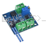
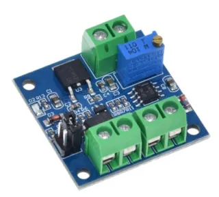
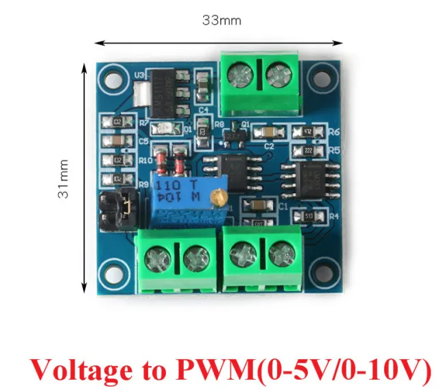
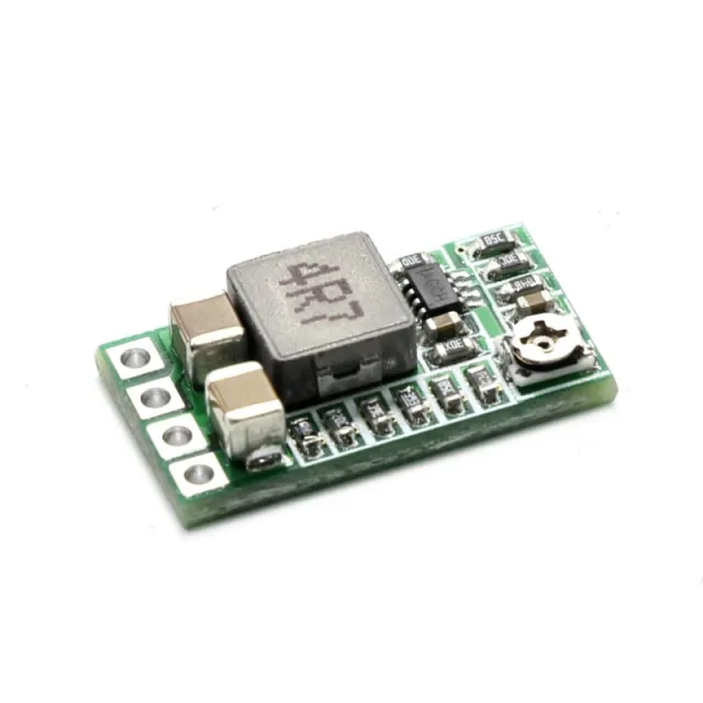
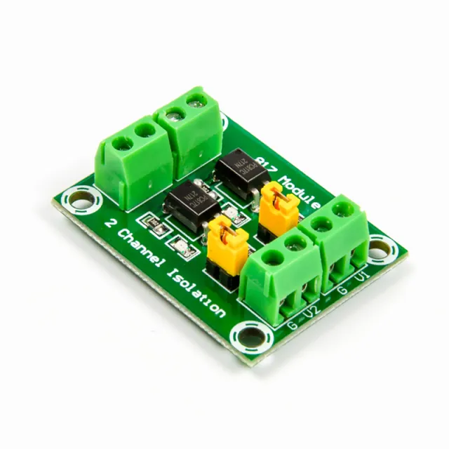
PWM to Voltage converter module 0-10V

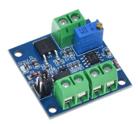
This PWM to Voltage Converter Module is designed to convert PWM signals to a voltage between 0-10V, and is suitable for a wide range of applications in industry and electronics projects.

The module has a working voltage range of DC 12V-30V, with a minimum current of more than 100mA. Note, this is the voltage required to operate the module and is separate from the PWM signal.

The PWM signal frequency range is between 1KHZ-3KHZ, making the module compatible with a large number of devices and controllers.

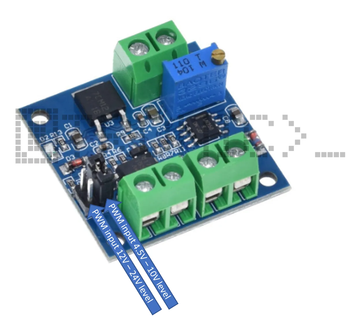
The PWM signal input level range can be set to 4.5 to 10V level (for conventional industrial control boards such as the MACH3 board and the interface of a 5V CPU) or to 12 to 24V level (mainly aimed at the conventional PLC interface).
With a jumper pin, this is set by default to 4.5 to 10V level.

The conversion range from PWM to voltage is 0%-100%, with a tolerance of 5%. This means you can easily adjust the output voltage between 0-10V by adjusting the PWM duty cycle.

The PWM to Voltage Converter Module is compact and easy to install and use. The module offers flexible options for adjusting the signal level, making it suitable for a wide range of applications, such as motor speed control, LED dimming, and temperature control.

Product specifications:

  • Working voltage range: DC 12V-30V
  • Power requirement: minimum 100mA
  • PWM signal reception frequency range: 1KHZ-3KHZ
  • PWM signal input voltage range: 4.5V to 10V or 12V to 24V (adjustable with jumper)
  • Voltage output range: 0-10V
  • Conversion range: 0%-100% PWM conversion to 0-10V voltage
  • Tolerance: 5%
  • Potentiometer for PWM signal calibration
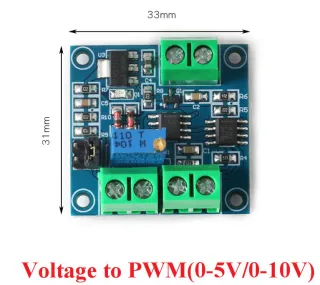
  • Module dimensions: (LxWxH) 33x33x15mm
  • Adjustable signal level
  • Compact size
  • Easy to install
  • 0-10V output

Why choose this product?

  • Adjustable input level – For 4.5-10V or 12-24V PWM level.
  • Wide frequency range – Works with 1KHZ-3KHZ PWM signals.
  • Compact size – Easy to install and use.
  • Suitable for applications – For motor control, LED dimming and temperature control.
Specifications
Tolerance5%
Operating voltage rangeDC 12V-30V
Power requirementminimum 100mA
PWM signal reception frequency range1KHZ-3KHZ
PWM signal input voltage range4.5V to 10V or 12V to 24V (adjustable with jumper)
Output voltage range0-10V
Conversion range0%-100% PWM conversion to 0-10V voltage
Module dimensions(LxWxH) 33x33x15mm

Frequently bought together

Total: € 9,40

Reviews

★★★★★ 4,8/5 6 reviews
  • ★★★★★Jean-marc Renaud

    not tested yet

  • ★★★★★jan dekker

    used to control 0-5V from the 12V E-scooter with PWM from the uController, works perfectly

  • ★★★★★Marc Bouyer

    Interesting to try

Write a review
Your rating

Shipping & returns

Shipping

  • Parcel with track & trace€ 7,70Within 24 hours
  • Pick up at PostNL location€ 7,40Within 24 hours
  • Letterbox parcel€ 3,70Within 2 business days
  • Letterbox parcel 24 hours€ 4,55Within 24 hours
  • Pick up in storeFree
All about shipping

Returns

Not satisfied? You have 30 days after delivery to return the product.

All about returns

Recently viewed