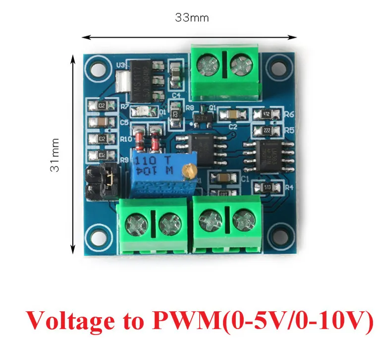
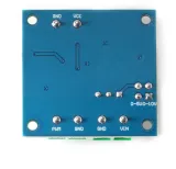
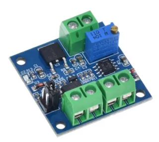
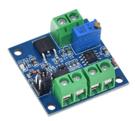
Module that converts 0-10V to PWM for adjustable voltage control.
SKU: OT3561 Article number: AA686 EAN: 8720618827449 Location: C08.01
Alternative
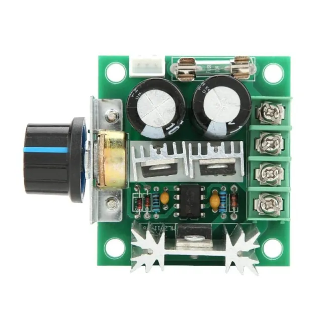
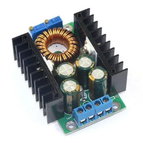
12V-40V 10A DC motor PWM speed controller
€ 3,50
View this alternative
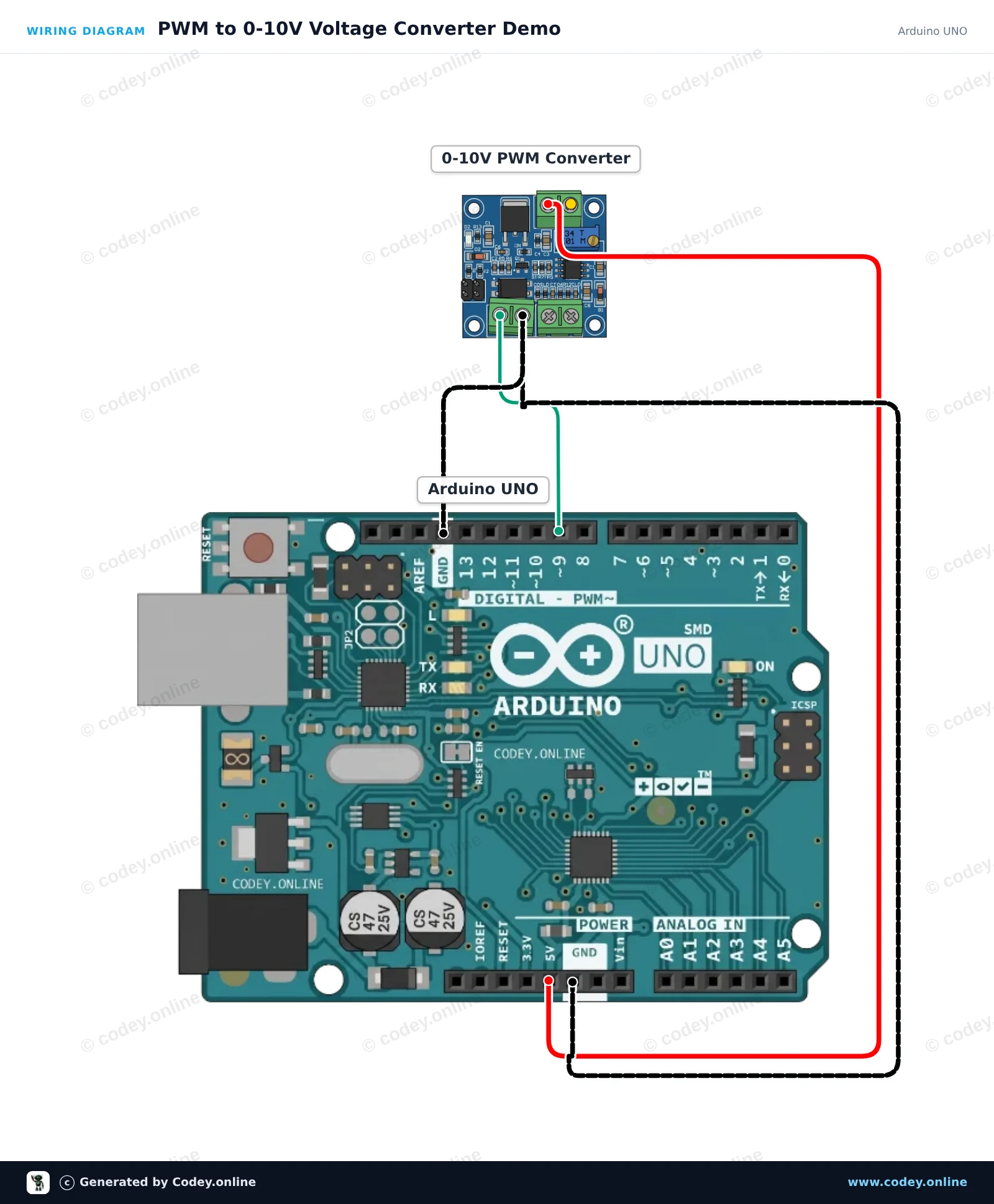
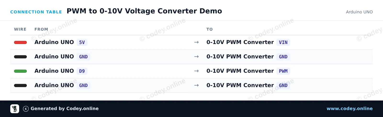
How to connect the Voltage to PWM Converter Module 0-10V to an Arduino UNO or ESP32, with an example sketch you can upload straight away.
This circuit generates a varying PWM signal on pin 9, which the converter module transforms into a proportional DC analog output voltage (0-10V). Open the Serial Monitor to observe the current PWM duty cycle as it ramps smoothly up and down. Measure the VOUT terminal with a multimeter to verify the changing analog voltage.
/*
* ==================================================================
* Generated by Codey.online — https://www.codey.online
* ==================================================================
* Project : PWM to 0-10V Voltage Converter Demo
* Board : Arduino UNO (arduino:avr:uno)
* Parts : PWM naar Voltage converter module 0-10V
* Libraries : none (built-in)
*
* Codey Online is an AI-powered browser IDE for Arduino and ESP32.
* Describe your project and Codey writes the code, draws the wiring
* diagram and uploads it to your board, straight from the browser.
* This code is free to use, modify and share, without warranty.
* ==================================================================
*/
// PWM to 0-10V Voltage Converter Module Demo
// Sweeps PWM duty cycle on pin 9 from 0% to 100% and back
const int pwmPin = 9;
void setup() {
pinMode(pwmPin, OUTPUT);
Serial.begin(115200);
Serial.println(F("PWM to 0-10V Converter Demo Initialized"));
}
void loop() {
// Ramp up
for (int duty = 0; duty <= 255; duty += 5) {
analogWrite(pwmPin, duty);
Serial.print(F("PWM Duty: "));
Serial.print(duty);
Serial.print(F("/255 ("));
Serial.print((duty * 100) / 255);
Serial.println(F("%)"));
delay(50);
}
delay(500);
// Ramp down
for (int duty = 255; duty >= 0; duty -= 5) {
analogWrite(pwmPin, duty);
Serial.print(F("PWM Duty: "));
Serial.print(duty);
Serial.print(F("/255 ("));
Serial.print((duty * 100) / 255);
Serial.println(F("%)"));
delay(50);
}
delay(500);
}
Wiring diagram and example code generated by Codey.online — https://www.codey.online
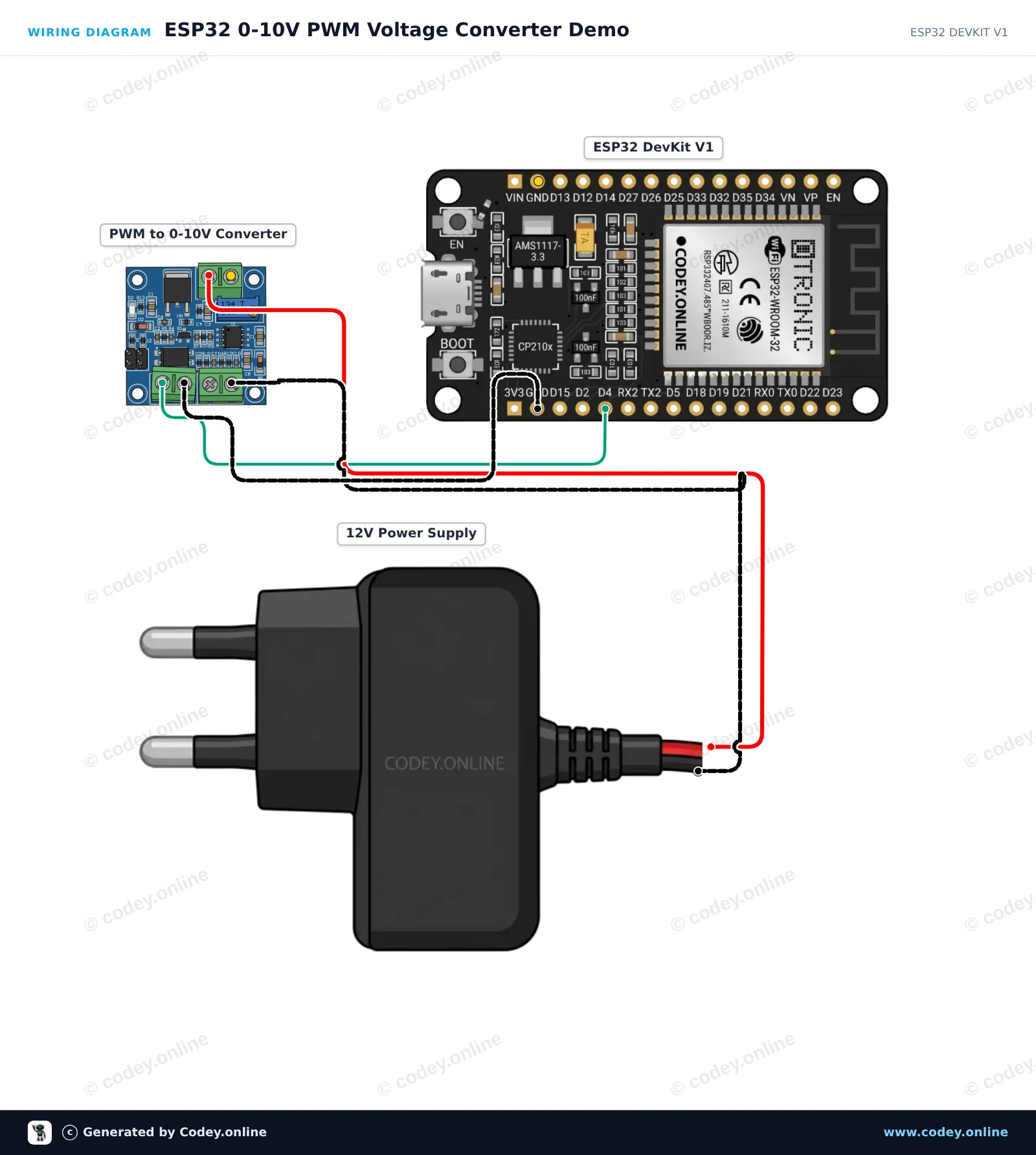
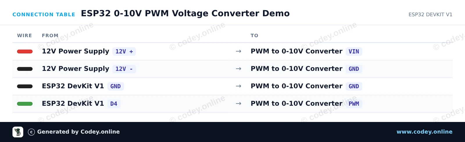
This project demonstrates generating a 0-10V analog control voltage using an ESP32 and a PWM-to-voltage converter module. The ESP32 sends a 0-100% PWM signal from GPIO 4 to the module, which converts it into a proportional 0-10V DC output suitable for PLCs, VFDs, and dimmers. An external 12V power supply powers the converter module.
/*
* ==================================================================
* Generated by Codey.online — https://www.codey.online
* ==================================================================
* Project : ESP32 0-10V PWM Voltage Converter Demo
* Board : ESP32 DEVKIT V1 (esp32:esp32:esp32doit-devkit-v1)
* Parts : PWM naar Voltage converter module 0-10V
* Libraries : none (built-in)
*
* Codey Online is an AI-powered browser IDE for Arduino and ESP32.
* Describe your project and Codey writes the code, draws the wiring
* diagram and uploads it to your board, straight from the browser.
* This code is free to use, modify and share, without warranty.
* ==================================================================
*/
/*
* PWM to 0-10V Voltage Converter Demo
* Board: ESP32 DevKit V1
*
* Ramps output voltage from 0V to 10V and back down.
*/
const int PWM_PIN = 4; // GPIO 4 connected to PWM input
void setup() {
Serial.begin(115200);
pinMode(PWM_PIN, OUTPUT);
Serial.println("PWM to 0-10V Converter Demo Started");
}
void loop() {
// Ramp up from 0V to 10V
for (int duty = 0; duty <= 255; duty += 5) {
analogWrite(PWM_PIN, duty);
float expectedVoltage = (duty / 255.0) * 10.0;
Serial.print("Duty: ");
Serial.print(duty);
Serial.print("/255 | Output Voltage: ~");
Serial.print(expectedVoltage, 2);
Serial.println(" V");
delay(50);
}
delay(500);
// Ramp down from 10V to 0V
for (int duty = 255; duty >= 0; duty -= 5) {
analogWrite(PWM_PIN, duty);
float expectedVoltage = (duty / 255.0) * 10.0;
Serial.print("Duty: ");
Serial.print(duty);
Serial.print("/255 | Output Voltage: ~");
Serial.print(expectedVoltage, 2);
Serial.println(" V");
delay(50);
}
delay(500);
}
Wiring diagram and example code generated by Codey.online — https://www.codey.online
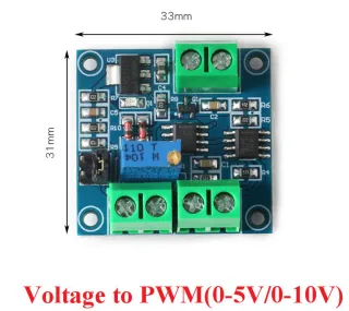
This module converts a voltage of 0V - 10V into a PWM signal
Specifications for the Voltage to PWM converter:
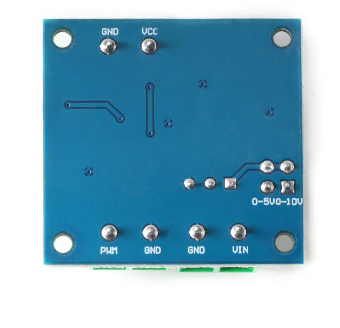
Connections:
VCC: + Operating voltage 5V-12V (power supply for the board itself)
GND: - Operating voltage 5V-12V
VIN: + Input voltage 0-10V (this is converted to PWM)
GND: - Input voltage 0-10V
GND: - PWM output
PWM: + PWM output
Operation:
Connect the operating voltage to VCC and GND. Do not connect them in reverse to prevent damage to the PCB and devices. Connect an adjustable voltage to the VIN terminal. The voltage range is divided into two types: 0-5V and 0-10V depending on the mode selected with the jumper. This is shown on the back of the board. By default, it is set to 0-5V.
The output is PWM. The duty cycle can be adjusted by changing the voltage. The accuracy can be checked by adjusting the potentiometer.

| Operating voltage | DC 5V-12V |
|---|---|
| Input voltage | 0-10V |
| Tolerance | 1%-3% |
| PWM Frequency | approximately 50KHZ |
| Conversion range | 0-5V/0-10V |
| PWM amplitude | 5V |
| Voltage conversion | 0%-100% PWM |
Customer order
Does exactly what I bought it for
not tested yet
Board works as expected
Voltage to PWM Converter Module 0-10V