Ordered on weekdays before 14:00 = shipped the same day and delivered the next day in 98% of cases. Free returns 30-day reflection period 1-year warranty

Wiring diagram and code example

How to connect the Relay Module 5V Low to an Arduino UNO or ESP32, with an example sketch you can upload straight away.

5V Active-Low Relay Control

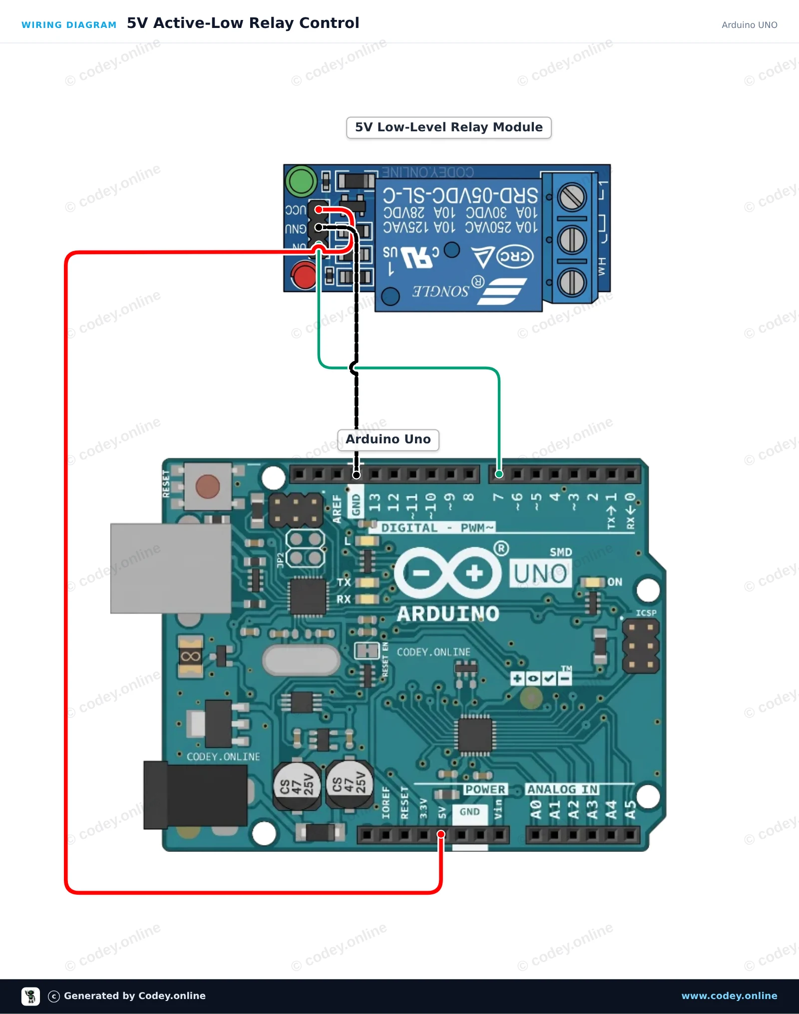
This project demonstrates how to control a 5V active-low relay module with an Arduino Uno. The sketch toggles the relay ON and OFF every two seconds while printing the current state to the Serial Monitor. Because this is an active-low module, setting the control pin LOW activates the relay, and setting it HIGH deactivates it.

Wiring diagram: Relay Module 5V Low on an Arduino UNO
Wiring diagram · Click to enlarge
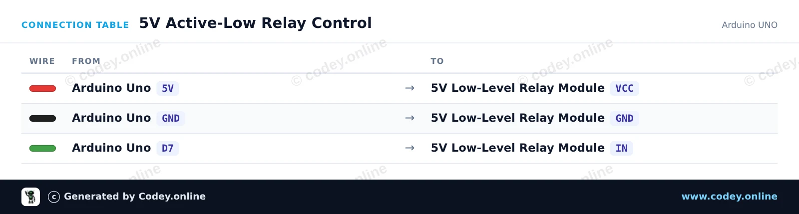
Connection table: Relay Module 5V Low on an Arduino UNO
Connection table · Click to enlarge
5V_Active_Low_Relay_Control.ino · compiled and verified
/*
 * ==================================================================
 *  Generated by Codey.online  —  https://www.codey.online
 * ==================================================================
 *  Project   : 5V Active-Low Relay Control
 *  Board     : Arduino UNO (arduino:avr:uno)
 *  Parts     : Relais Module 5v Low
 *  Libraries : none (built-in)
 *
 *  Codey Online is an AI-powered browser IDE for Arduino and ESP32.
 *  Describe your project and Codey writes the code, draws the wiring
 *  diagram and uploads it to your board, straight from the browser.
 *  This code is free to use, modify and share, without warranty.
 * ==================================================================
 */

// Pin configuration
const int relayPin = 7;

void setup() {
  // Set the relay pin as output
  pinMode(relayPin, OUTPUT);
  
  // Active-low relay: default to OFF (HIGH state)
  digitalWrite(relayPin, HIGH);

  Serial.begin(115200);
  while (!Serial) {
    ; // Wait for serial port to connect
  }

  Serial.println(F("5V Relay Module Demo Started"));
  Serial.println(F("Relay will toggle every 2 seconds."));
}

void loop() {
  // Turn relay ON (active LOW)
  Serial.println(F("Relay: ON"));
  digitalWrite(relayPin, LOW);
  delay(2000);

  // Turn relay OFF (HIGH)
  Serial.println(F("Relay: OFF"));
  digitalWrite(relayPin, HIGH);
  delay(2000);
}

Wiring diagram and example code generated by Codey.online — https://www.codey.online

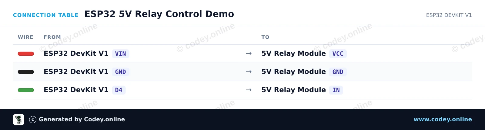
ESP32 5V Relay Control Demo

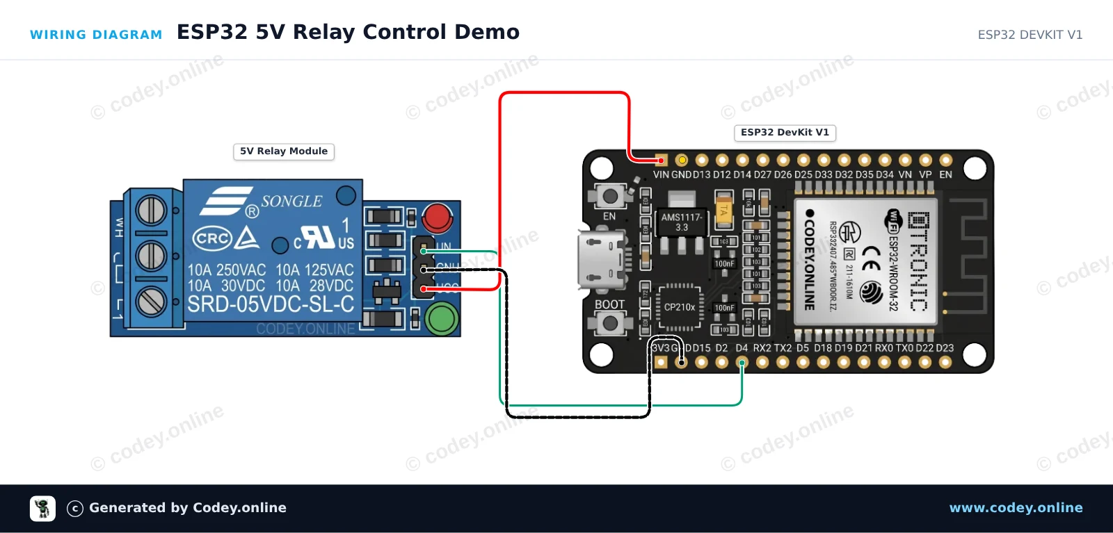
This example demonstrates how to control a 5V active-low relay module with the ESP32. The relay's coil is powered from the VIN pin (5V from USB) while GPIO 4 toggles the control pin. Driving the control pin LOW energizes the relay switch, and driving it HIGH turns it off.

Wiring diagram: Relay Module 5V Low on an ESP32 DevKit V1
Wiring diagram · Click to enlarge
Connection table: Relay Module 5V Low on an ESP32 DevKit V1
Connection table · Click to enlarge
ESP32_5V_Relay_Control_Demo.ino · compiled and verified
/*
 * ==================================================================
 *  Generated by Codey.online  —  https://www.codey.online
 * ==================================================================
 *  Project   : ESP32 5V Relay Control Demo
 *  Board     : ESP32 DEVKIT V1 (esp32:esp32:esp32doit-devkit-v1)
 *  Parts     : Relais Module 5v Low
 *  Libraries : none (built-in)
 *
 *  Codey Online is an AI-powered browser IDE for Arduino and ESP32.
 *  Describe your project and Codey writes the code, draws the wiring
 *  diagram and uploads it to your board, straight from the browser.
 *  This code is free to use, modify and share, without warranty.
 * ==================================================================
 */

// Pin connected to relay IN
const int RELAY_PIN = 4;

void setup() {
  Serial.begin(115200);
  
  // Configure relay pin as output and start with relay OFF (HIGH = inactive for active-low module)
  pinMode(RELAY_PIN, OUTPUT);
  digitalWrite(RELAY_PIN, HIGH);
  
  Serial.println("ESP32 Relay Module Demo Initialized");
}

void loop() {
  // Turn relay ON (Active-low: LOW energizes coil)
  Serial.println("Relay: ON");
  digitalWrite(RELAY_PIN, LOW);
  delay(2000);

  // Turn relay OFF (Active-low: HIGH de-energizes coil)
  Serial.println("Relay: OFF");
  digitalWrite(RELAY_PIN, HIGH);
  delay(2000);
}

Wiring diagram and example code generated by Codey.online — https://www.codey.online

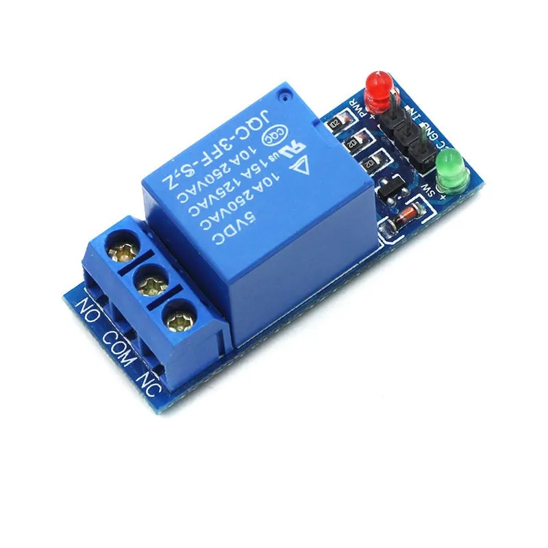
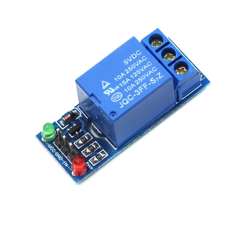
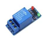
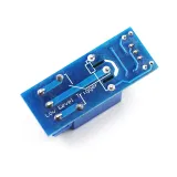
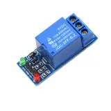
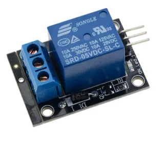
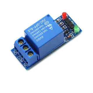
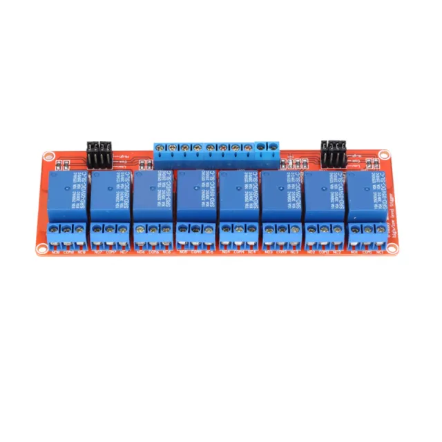
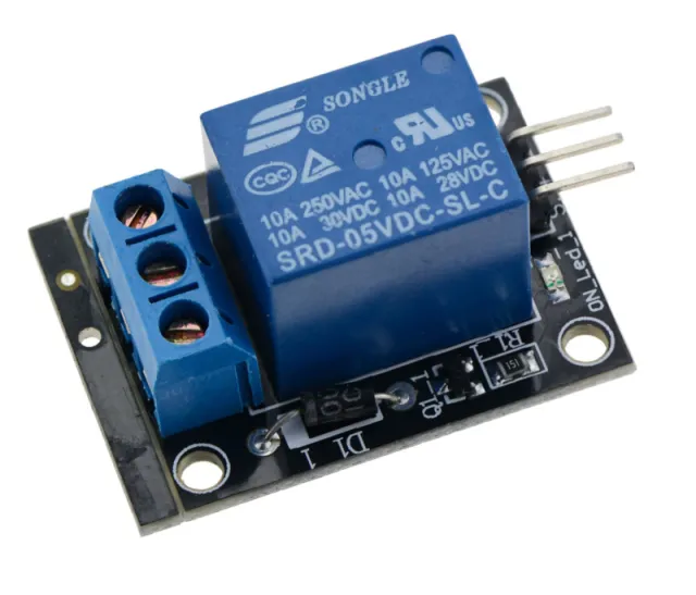
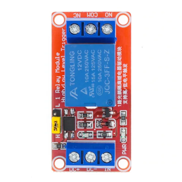
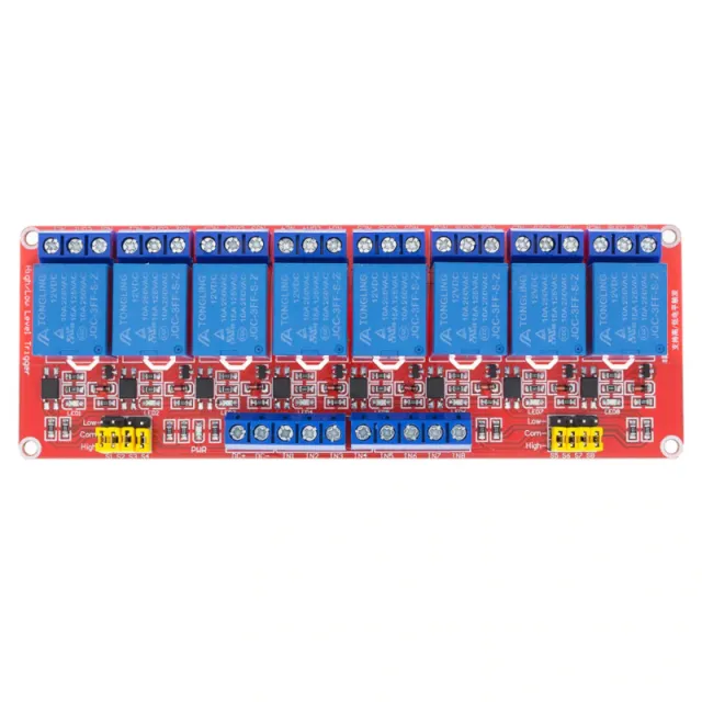
Relay Module 5V Low

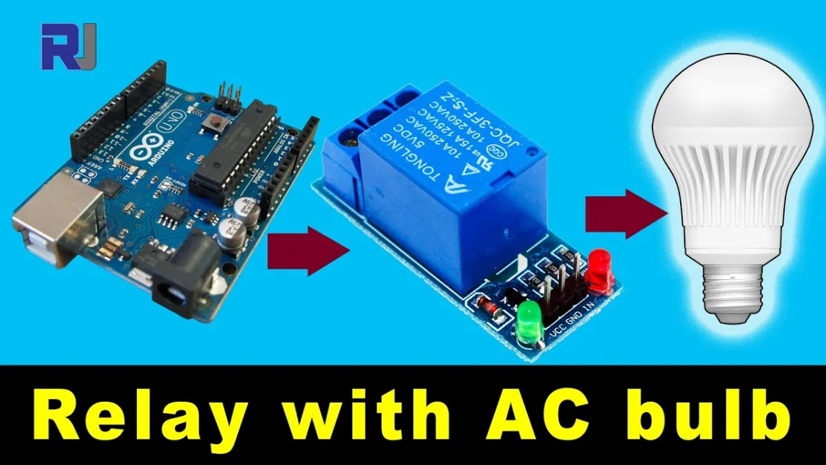
  • High load possible: AC250V 10A / DC30V 10A
  • Relay control 5V
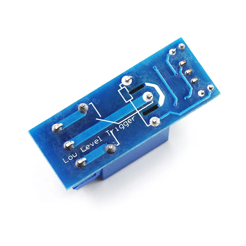
  • Signal: low
  • 1 relay on PCB
  • with LED indicators, red and green

view the Wiring diagram and example code >>> here

Search terms: relay 5v, 5v relay, relay 5v, 5v relay, relay low, relay low, relay low, blue relay, relay blue, relay 250v, relay 220v, relay 1 channel, relay 1-channel, relay 1 channel

  • 5V control
  • Low signal
  • AC250V 10A
  • LED indicators
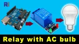
Playing loads the video from YouTube.

Why choose this product?

  • 5V control – Suitable for relay control with 5V.
  • High load – Switches up to AC250V 10A or DC30V 10A.
  • Single relay – One relay on the circuit board.
  • Status indication – With red and green LED indicators.
Specifications
Power supply5 V
Type1-channel
High load possibleAC250V 10A / DC30V 10 A
Signallow

Frequently bought together

Total: € 8,54

Reviews

★★★★★ 4,0/5 1 review
  • ★★★★★Jan

    Fine and works well

Write a review
Your rating

Shipping & returns

Shipping

  • Parcel with track & trace€ 7,70Within 24 hours
  • Pick up at PostNL location€ 7,40Within 24 hours
  • Letterbox parcel€ 3,70Within 2 business days
  • Letterbox parcel 24 hours€ 4,55Within 24 hours
  • Pick up in storeFree
All about shipping

Returns

Not satisfied? You have 30 days after delivery to return the product.

All about returns

Recently viewed

Potentiometer 1K Linear

Potentiometer 1K Linear

€ 0,90
Soil moisture sensor 5v

Soil moisture sensor 5v

€ 3,70
Potentiometer 1M Linear

Potentiometer 1M Linear

€ 0,90
DS1302 Real Time Clock Module

DS1302 Real Time Clock Module

€ 1,60
Servo Tester

Servo Tester

€ 3,49