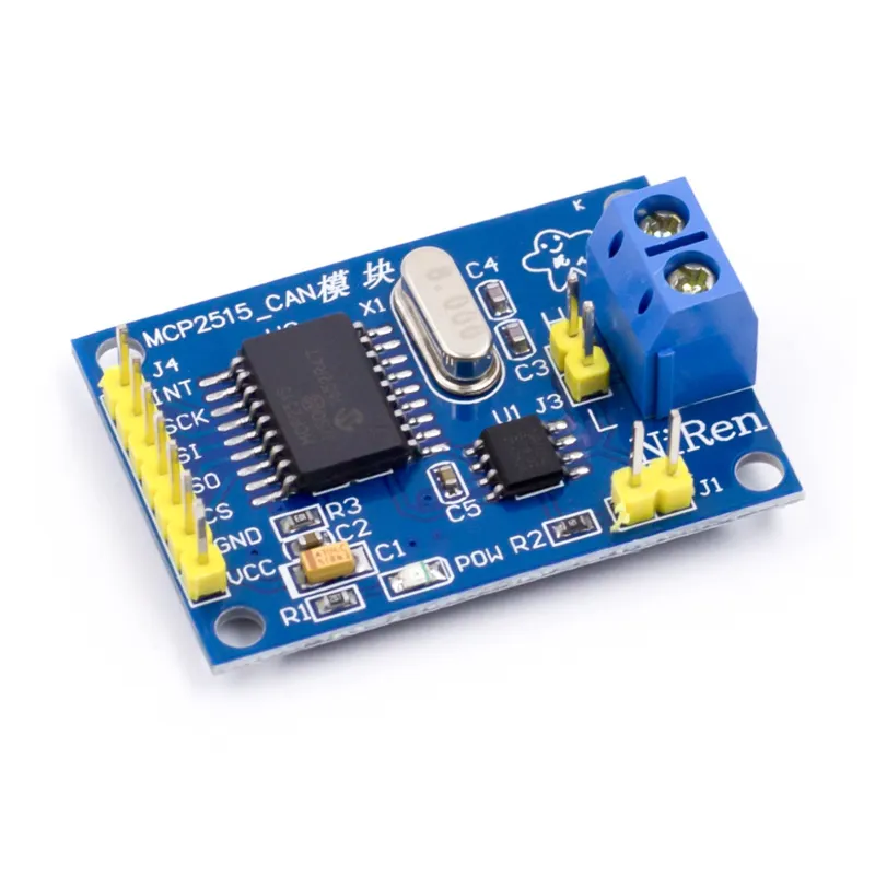
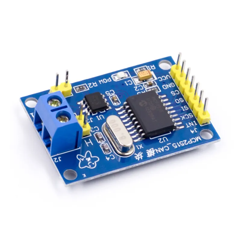
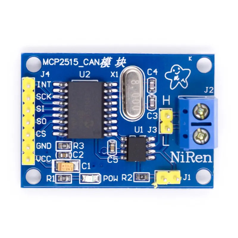
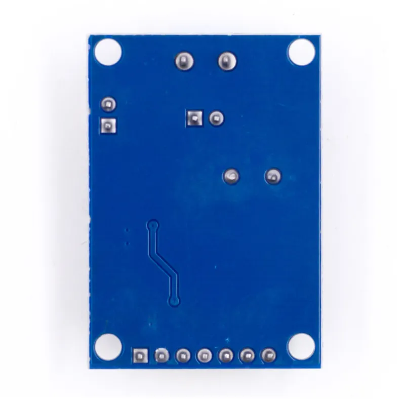
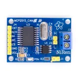
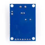
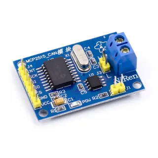
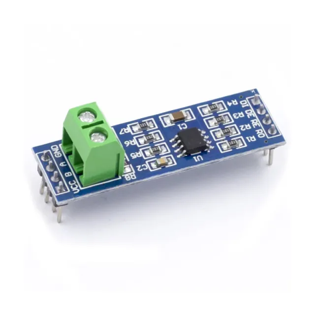
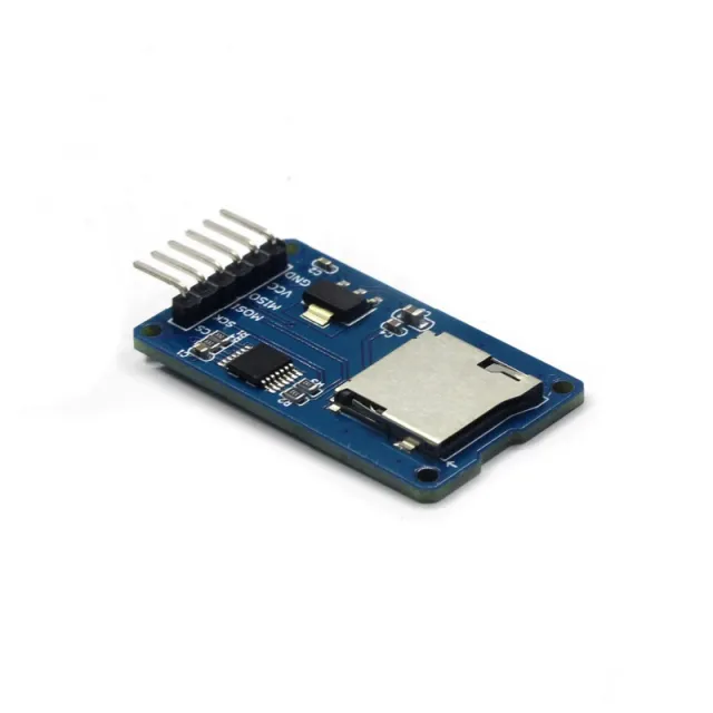
CAN bus module for Arduino and other microcontroller projects that communicate via SPI with a CAN bus system.
SKU: OT2083-D99 Article number: AA204 EAN: 4374044390615 Location: D09.09
Alternative
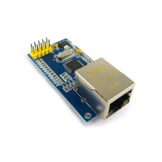
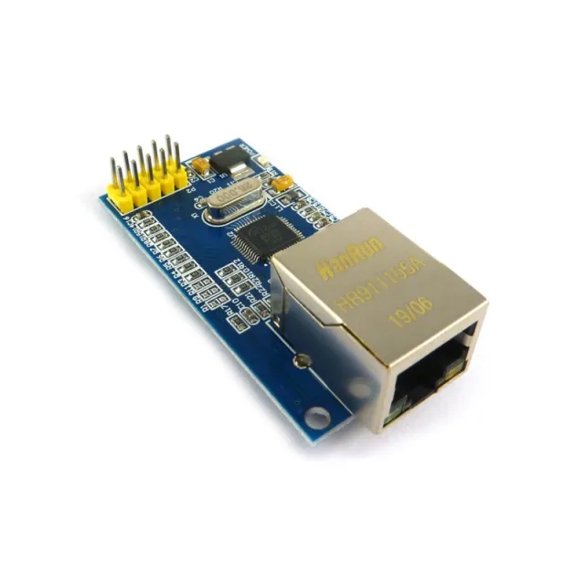
SPI Ethernet module W5500
€ 7,65
View this alternative
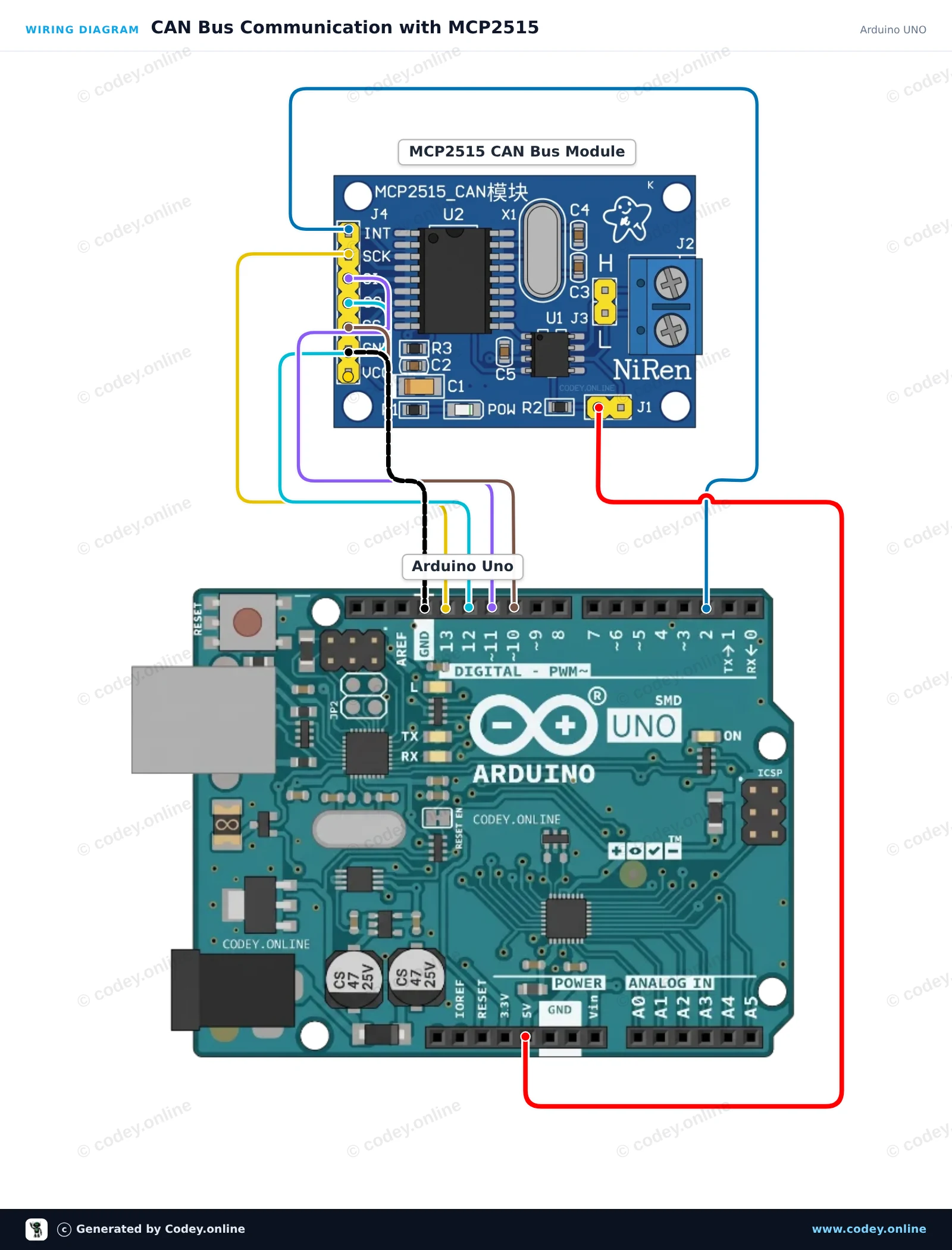
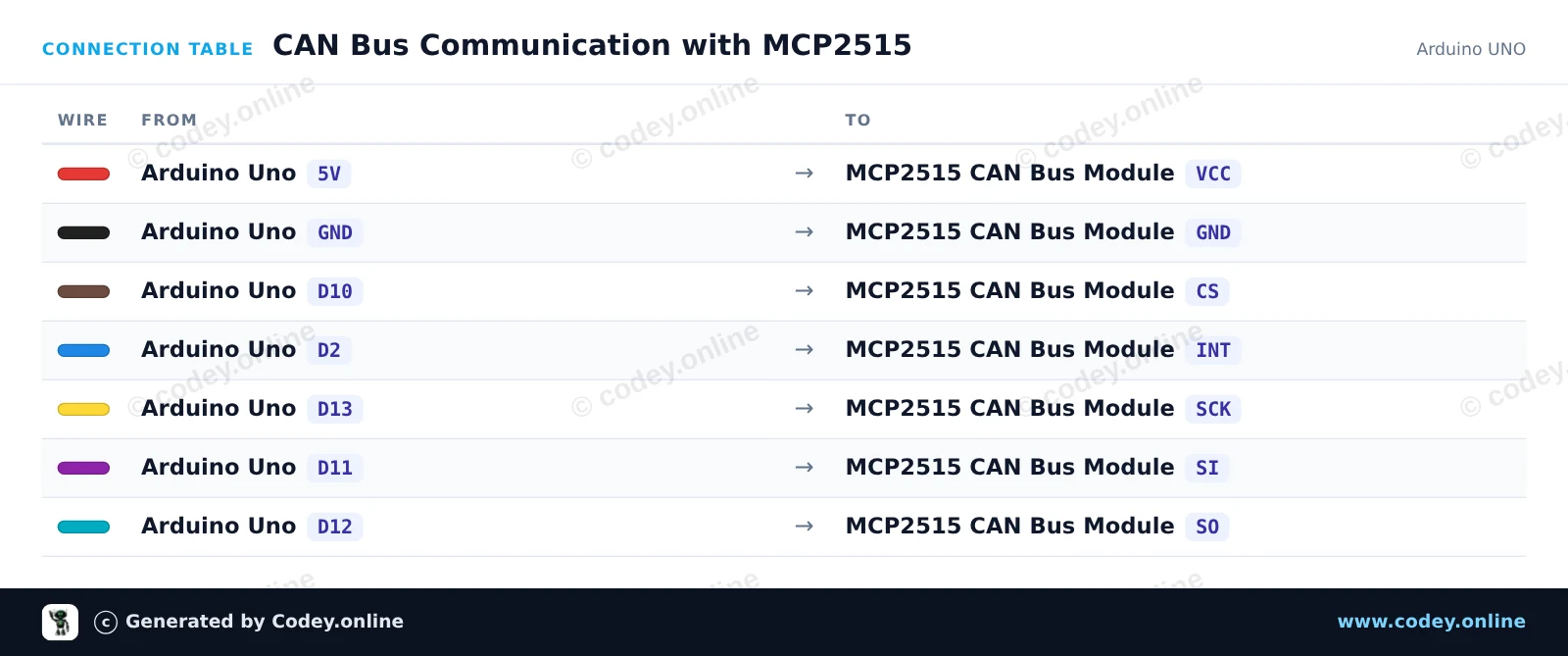
How to connect the CAN bus module MCP2515 SPI 5V to an Arduino UNO or ESP32, with an example sketch you can upload straight away.
Connects an MCP2515 CAN bus module to an Arduino Uno using hardware SPI. The sketch initializes the CAN controller at 500 kbps, sends a test CAN message every 2 seconds, and prints any received frames to the Serial Monitor.
/*
* ==================================================================
* Generated by Codey.online — https://www.codey.online
* ==================================================================
* Project : CAN Bus Communication with MCP2515
* Board : Arduino UNO (arduino:avr:uno)
* Parts : CAN-bus module MCP2515 SPI 5V
* Libraries : mcp_can 1.5.1
*
* Codey Online is an AI-powered browser IDE for Arduino and ESP32.
* Describe your project and Codey writes the code, draws the wiring
* diagram and uploads it to your board, straight from the browser.
* This code is free to use, modify and share, without warranty.
* ==================================================================
*/
#include <SPI.h>
#include <mcp_can.h>
const byte CAN_CS_PIN = 10;
const byte CAN_INT_PIN = 2;
MCP_CAN CAN(CAN_CS_PIN);
unsigned long lastSend = 0;
void setup() {
Serial.begin(115200);
pinMode(CAN_INT_PIN, INPUT);
// Initialize MCP2515 with standard 8MHz crystal at 500 kbps
if (CAN.begin(MCP_ANY, CAN_500KBPS, MCP_8MHZ) == CAN_OK) {
Serial.println(F("MCP2515 initialized successfully!"));
} else {
Serial.println(F("MCP2515 initialization failed!"));
while (1);
}
CAN.setMode(MCP_NORMAL);
Serial.println(F("CAN controller ready in normal mode."));
}
void loop() {
// Check for received CAN messages
if (CAN.checkReceive() == CAN_MSGAVAIL) {
unsigned long rxId;
byte len = 0;
byte rxBuf[8];
CAN.readMsgBuf(&rxId, &len, rxBuf);
Serial.print(F("RX -> ID: 0x"));
Serial.print(rxId, HEX);
Serial.print(F(" DLC: "));
Serial.print(len);
Serial.print(F(" Data: "));
for (byte i = 0; i < len; i++) {
if (rxBuf[i] < 0x10) Serial.print('0');
Serial.print(rxBuf[i], HEX);
Serial.print(' ');
}
Serial.println();
}
// Send a test packet every 2 seconds
if (millis() - lastSend >= 2000) {
lastSend = millis();
byte txData[4] = {0xDE, 0xAD, 0xBE, 0xEF};
byte sndStat = CAN.sendMsgBuf(0x100, 0, 4, txData);
if (sndStat == CAN_OK) {
Serial.println(F("TX -> Sent frame (ID: 0x100, Data: DE AD BE EF)"));
} else {
Serial.println(F("TX -> Error sending message"));
}
}
}
Required libraries: mcp_can 1.5.1
Wiring diagram and example code generated by Codey.online — https://www.codey.online
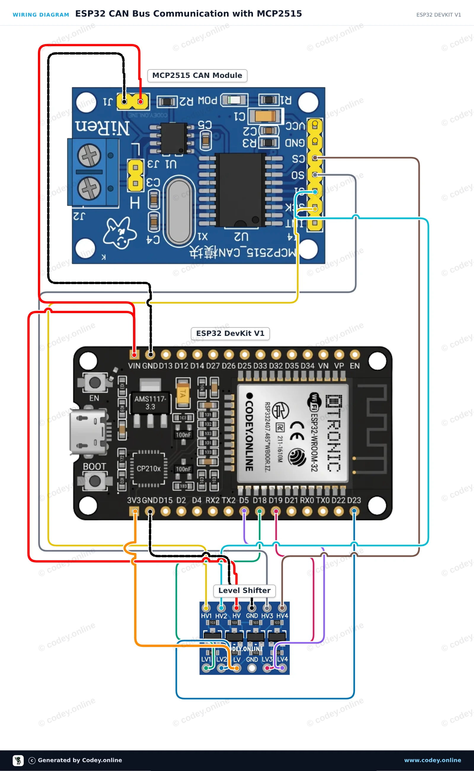
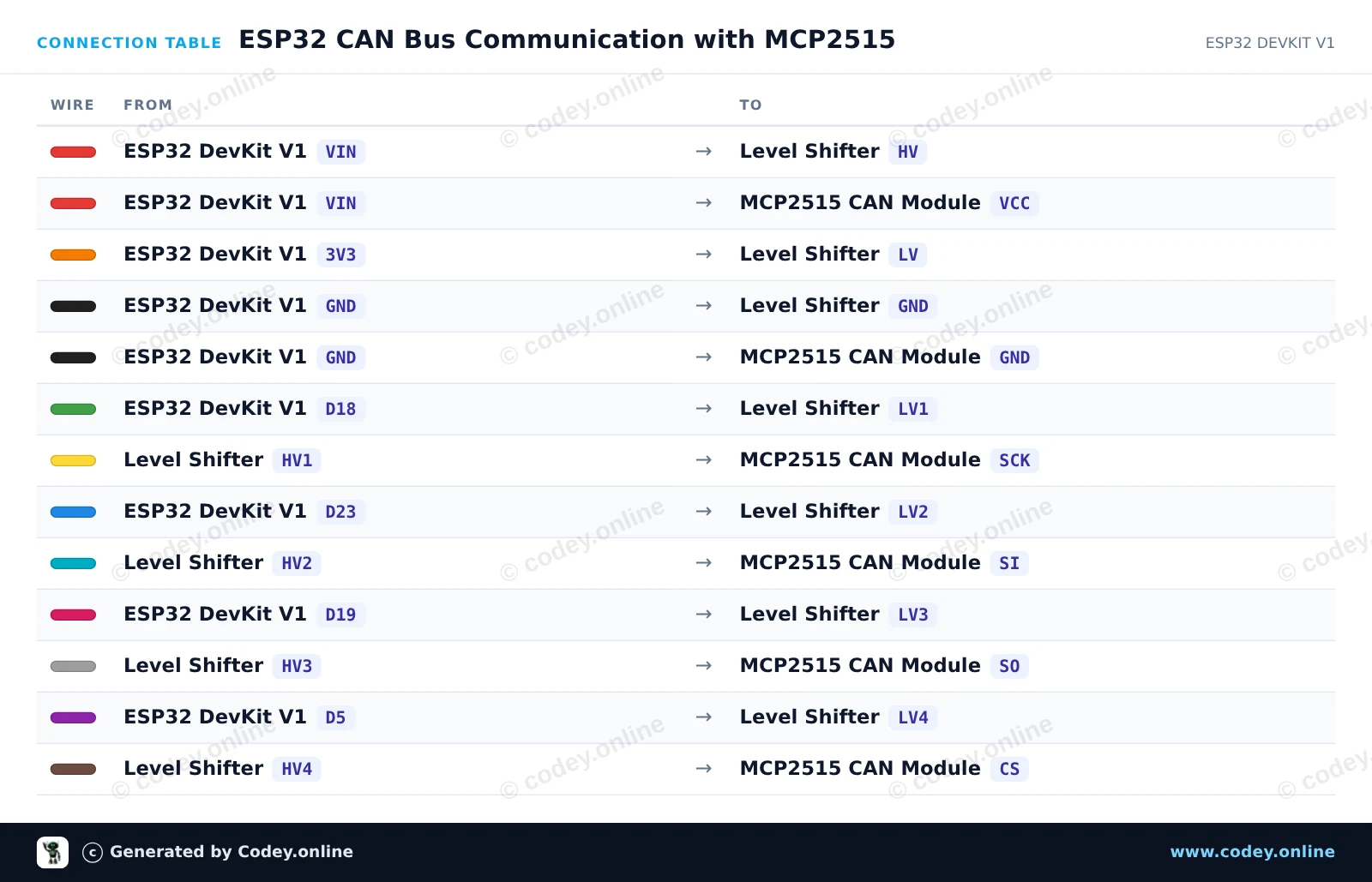
This circuit connects an ESP32 to an MCP2515 CAN-bus module via SPI, using a 4-channel bidirectional level shifter to protect the ESP32's 3.3V logic from the 5V module. The sketch initializes the CAN controller at 500 kbps, sends a test CAN data frame every two seconds, and prints any received CAN bus messages to the Serial Monitor.
/*
* ==================================================================
* Generated by Codey.online — https://www.codey.online
* ==================================================================
* Project : ESP32 CAN Bus Communication with MCP2515
* Board : ESP32 DEVKIT V1 (esp32:esp32:esp32doit-devkit-v1)
* Parts : CAN-bus module MCP2515 SPI 5V
* Libraries : mcp_can 1.5.1
*
* Codey Online is an AI-powered browser IDE for Arduino and ESP32.
* Describe your project and Codey writes the code, draws the wiring
* diagram and uploads it to your board, straight from the browser.
* This code is free to use, modify and share, without warranty.
* ==================================================================
*/
#include <SPI.h>
#include <mcp_can.h>
const int CAN_CS_PIN = 5;
MCP_CAN CAN0(CAN_CS_PIN);
void setup() {
Serial.begin(115200);
while (!Serial);
// Initialize MCP2515 running at 8MHz clock and 500kbps CAN baud rate
if (CAN0.begin(MCP_ANY, CAN_500KBPS, MCP_8MHZ) == CAN_OK) {
Serial.println("MCP2515 Initialized Successfully!");
} else {
Serial.println("Error Initializing MCP2515...");
}
CAN0.setMode(MCP_NORMAL);
}
void loop() {
// Prepare sample data payload (8 bytes)
byte data[8] = {0x11, 0x22, 0x33, 0x44, 0x55, 0x66, 0x77, 0x88};
// Send CAN message with standard ID 0x100
byte sndStat = CAN0.sendMsgBuf(0x100, 0, 8, data);
if (sndStat == CAN_OK) {
Serial.println("CAN Message Sent Successfully!");
} else {
Serial.println("Error Sending CAN Message...");
}
// Check for incoming CAN messages
if (CAN0.checkReceive() == CAN_MSGAVAIL) {
long unsigned int rxId;
unsigned char len = 0;
unsigned char rxBuf[8];
CAN0.readMsgBuf(&rxId, &len, rxBuf);
Serial.print("Received ID: 0x");
Serial.print(rxId, HEX);
Serial.print(" Data: ");
for (byte i = 0; i < len; i++) {
Serial.print("0x");
if (rxBuf[i] < 0x10) Serial.print("0");
Serial.print(rxBuf[i], HEX);
Serial.print(" ");
}
Serial.println();
}
delay(2000);
}
Required libraries: mcp_can 1.5.1
Wiring diagram and example code generated by Codey.online — https://www.codey.online
The MCP2515 CAN-bus module is suitable for Arduino and other microcontroller projects where you want to communicate with a CAN bus system using the SPI protocol.
Supports CAN V2.0B with a communication speed of 1 Mb/s.
Supply voltage: 5V
Interface: controllable with SPI
Dimensions: approximately 2.8 x 4.8 cm
Dimensions
Length: 4cm
Width: 2.8cm
Height: 1.2cm

| Width | 2,8 cm |
|---|---|
| Length | 4 cm |
| Supply voltage | 5V |
| Height | 1,2 cm |
| CAN version | V2.0B |
| Communication speed | 1 Mb/s |
No reviews yet.
CAN bus module MCP2515 SPI 5V