




Ship to all EU countries
Art: AK041EAN: 8721244303086
ESP32-S3 Super Mini - Small & Powerful IoT Development Board with 4MB Flash & 2MB PSRAM (OT9921)
Show all:
ESP32





Would you like to order large quantities of this product or do you need a quote to order within your organization? Then request a quote.
REQUEST QUOTEThank you for your request.
You will receive the quote in your mailbox within a few minutes.
You will receive the quote in your mailbox within a few minutes.
Ship to all EU countries
Ordered on working days before 14:00 AM = shipped the same day.
30 days cooling-off period
1 jaar garantie
Description
ESP32-S3 Super Mini 4MB Flash and 2MB PSRAM
The ESP32-S3 Super Mini is a small and powerful development board for IoT, home automation, sensors, displays, USB devices, and embedded electronics. The board features a fast dual-core ESP32-S3 processor, built-in WiFi, Bluetooth Low Energy, native USB, 4 MB flash memory, and 2 MB PSRAM.
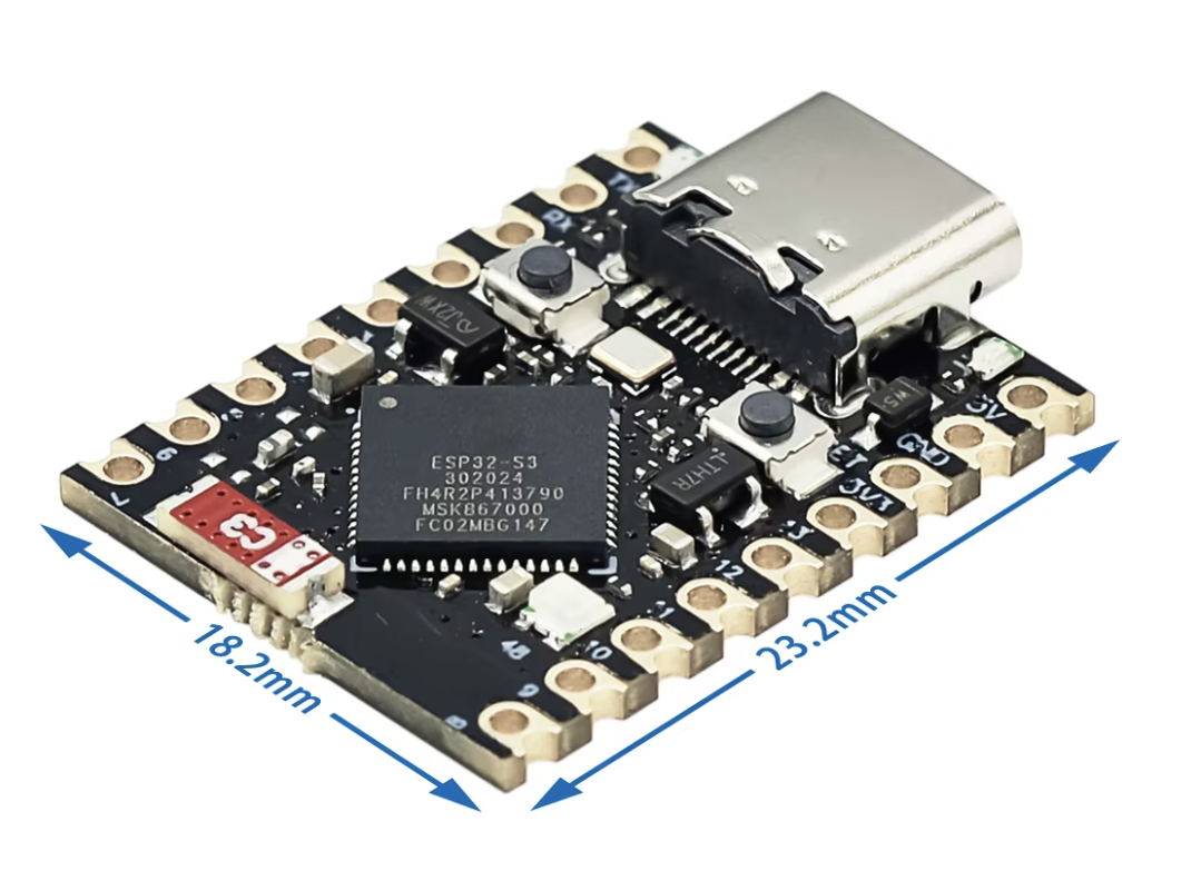
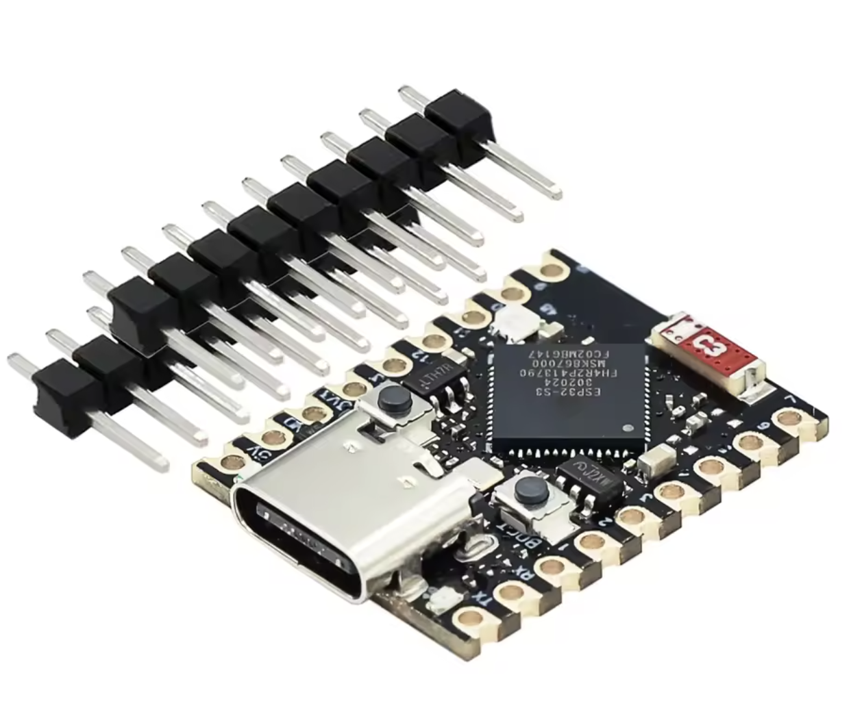
With a size of approximately 22.52 × 18 mm, this board offers a lot of computing power and connectivity options in a small footprint. The standard 2.54 mm pin spacing makes integration into various projects easy. The supplied pin headers need to be soldered by yourself.
Main Features
- ESP32-S3 dual-core Xtensa LX7 processor up to 240 MHz
- 4 MB flash memory and 2 MB QSPI PSRAM
- 512 KB internal SRAM and 384 KB ROM
- 2.4 GHz WiFi and Bluetooth 5 Low Energy
- Native USB via USB-C, no extra USB-to-serial converter needed
- 32 GPIO pins, 16 ADC inputs
- Programmable WS2812 RGB LED and status LEDs
- Support for Arduino IDE, PlatformIO, ESP-IDF, ESPHome, and MicroPython
- Firmware upload via USB and OTA
- Compact size: approximately 22.52 × 18 mm
Technical Specifications
- Microcontroller: ESP32-S3
- Processor: Dual-core Xtensa LX7, 240 MHz
- Internal SRAM: 512 KB
- ROM: 384 KB
- Flash Memory: 4 MB
- PSRAM: 2 MB QSPI
- WiFi: 2.4 GHz IEEE 802.11 b/g/n
- Bluetooth: Bluetooth 5 Low Energy
- USB Connector: USB-C (native USB 2.0, USB OTG, USB Serial/JTAG)
- GPIO: 32 pins
- ADC: 16 inputs
- UART: Up to 3 controllers
- I²C: Up to 2 controllers
- SPI: Up to 4 controllers
- PWM: Up to 8 channels
- Logic Level: 3.3 V
- Power Supply: 5 V via USB-C or 5V pin
- Dimensions: Approximately 22.52 × 18 mm
- Pin Pitch: 2.54 mm
Connections and Pins
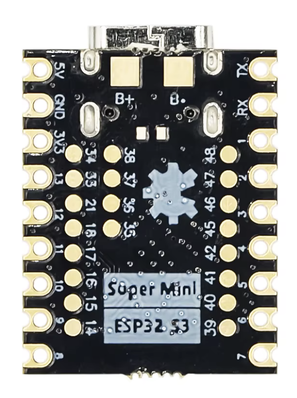
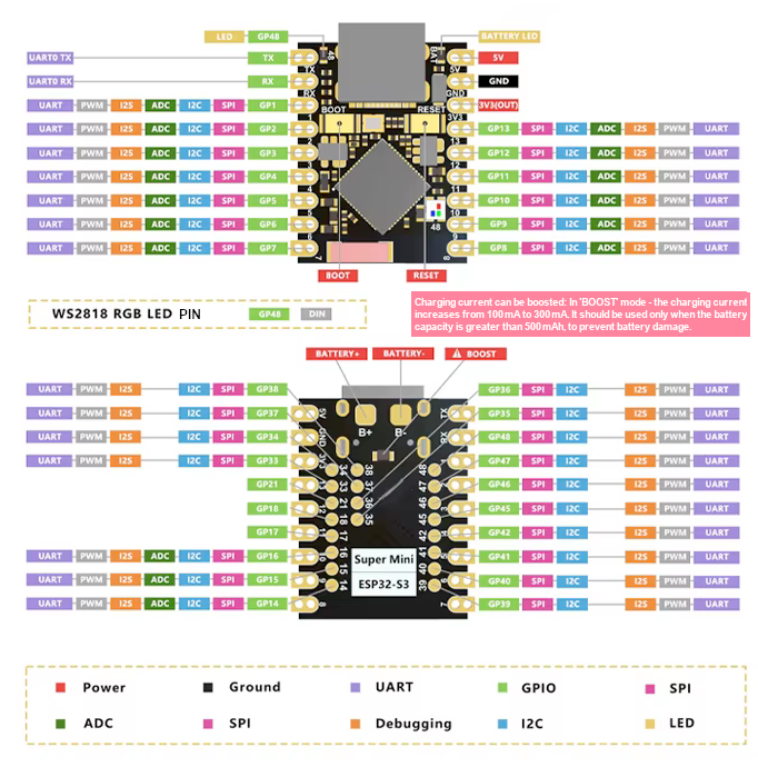
The board has 37 connection points, of which 32 can be used as GPIO. There are also connections for 5 V, 3.3 V, and GND. Commonly used GPIO pins without special functions during boot include:
- GPIO1, GPIO2, GPIO4, GPIO5, GPIO6, GPIO7, GPIO8
- GPIO15, GPIO16, GPIO17, GPIO18, GPIO21
Always check the pinout and software requirements for permanent connections, as some pins may have special functions during startup or debugging.
Built-in LEDs and Buttons
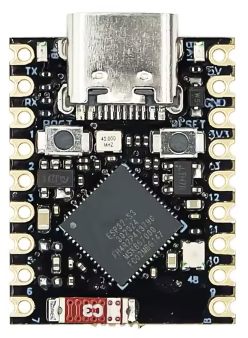
- Programmable WS2812 RGB LED (connected to GPIO48)
- Red status LED (connected to GPIO48)
- Blue charging status LED (for battery, not software controlled)
- BOOT button
- RESET button
Enabling PSRAM
The 2 MB PSRAM is not enabled by default in all development environments. In Arduino IDE, you must explicitly select "QSPI PSRAM" in the board settings. PlatformIO and ESPHome also require specific configurations to activate PSRAM.
Programming and Usage
The USB-C port is directly connected to the native USB interface, so no extra USB-to-serial converter is needed. For programming via Arduino IDE, "USB CDC On Boot" must be enabled.
If the board is not recognized or upload fails, follow these steps:
- Hold down the BOOT button
- Connect the USB cable or briefly press RESET
- Start the firmware upload
- Release the BOOT button
- Press RESET after upload to start the program
Communication and Peripherals
The ESP32-S3 Super Mini supports various interfaces: GPIO, ADC, PWM, UART, I²C, SPI, I²S, USB, WiFi, and Bluetooth Low Energy. This makes it suitable for sensors, relays, displays, LED strips, motor controllers, memory modules, and other digital or analog components.
Possible Applications
- IoT sensors and wireless measurement devices
- Home automation and control (Home Assistant, ESPHome, MQTT)
- Displays and graphical interfaces
- Data loggers and robotics
- USB HID devices, keyboards, and controllers
- LED strips and interactive lighting
- Bluetooth Low Energy devices
- Audio and voice processing
- Compact embedded systems and edge AI applications
Package Contents
- 1× ESP32-S3 Super Mini development board
- Matching pin headers (not soldered)
Note
- Pin headers must be soldered by yourself
- A USB-C cable with data support is required for programming
- GPIO operates at 3.3 V logic level and is not 5V tolerant
- Always check the pinout and function of connected components
Reviews
0/10
No reviews found
Add your reviewAlso interesting for you:



Kies je taal / Choose your language: