Ordered on weekdays before 14:00 = shipped the same day and delivered the next day in 98% of cases. Free returns 30-day reflection period 1-year warranty

Wiring diagram and code example

How to connect the 1.28″ round TFT LCD 240×240 (GC9A01, SPI) for Arduino to an Arduino UNO or ESP32, with an example sketch you can upload straight away.

1.28 Inch Round GC9A01 TFT LCD Demo

This project initializes and draws animated graphics on a 1.28-inch round SPI TFT display (GC9A01 controller). It draws colorful concentric rings around the circular screen and continuously cycles the color of an inner target circle.

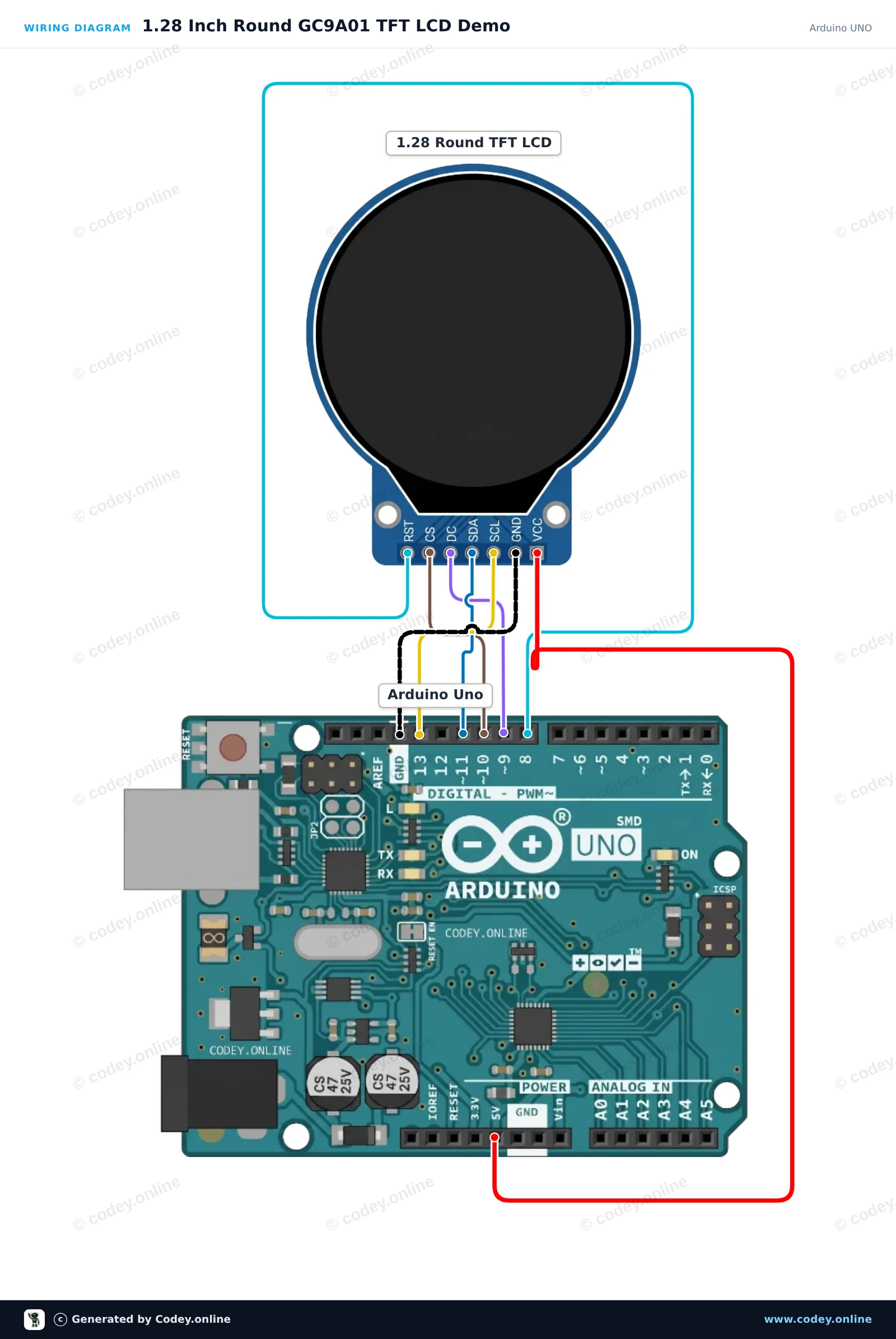
Wiring diagram: 1.28″ round TFT LCD 240×240 (GC9A01, SPI) for Arduino on an Arduino UNO
Wiring diagram · Click to enlarge
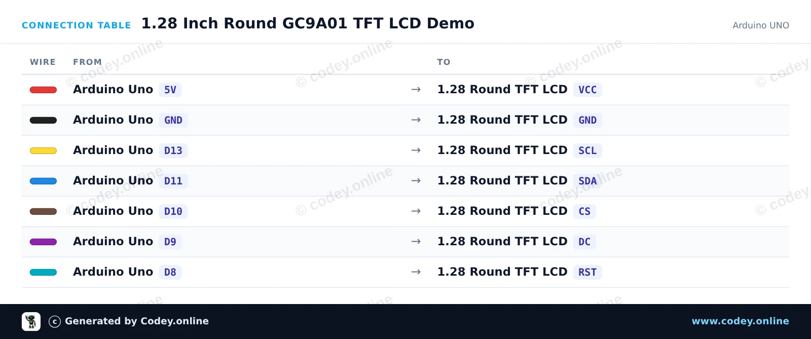
Connection table: 1.28″ round TFT LCD 240×240 (GC9A01, SPI) for Arduino on an Arduino UNO
Connection table · Click to enlarge
1_28_Inch_Round_GC9A01_TFT_LCD_Demo.ino · compiled and verified
/*
 * ==================================================================
 *  Generated by Codey.online  —  https://www.codey.online
 * ==================================================================
 *  Project   : 1.28 Inch Round GC9A01 TFT LCD Demo
 *  Board     : Arduino UNO (arduino:avr:uno)
 *  Parts     : 1.28" Round TFT LCD 240x240 (GC9A01, SPI)
 *  Libraries : none (built-in)
 *
 *  Codey Online is an AI-powered browser IDE for Arduino and ESP32.
 *  Describe your project and Codey writes the code, draws the wiring
 *  diagram and uploads it to your board, straight from the browser.
 *  This code is free to use, modify and share, without warranty.
 * ==================================================================
 */

#include <SPI.h>

#define TFT_CS   10
#define TFT_DC    9
#define TFT_RST   8

#define COLOR_BLACK   0x0000
#define COLOR_BLUE    0x001F
#define COLOR_RED     0xF800
#define COLOR_GREEN   0x07E0
#define COLOR_CYAN    0x07FF
#define COLOR_MAGENTA 0xF81F
#define COLOR_YELLOW  0xFFE0
#define COLOR_WHITE   0xFFFF

const uint16_t palette[] = {COLOR_RED, COLOR_GREEN, COLOR_BLUE, COLOR_YELLOW, COLOR_CYAN, COLOR_MAGENTA};
int colorIndex = 0;

void writeCommand(uint8_t c) {
  digitalWrite(TFT_DC, LOW);
  digitalWrite(TFT_CS, LOW);
  SPI.transfer(c);
  digitalWrite(TFT_CS, HIGH);
}

void writeData(uint8_t d) {
  digitalWrite(TFT_DC, HIGH);
  digitalWrite(TFT_CS, LOW);
  SPI.transfer(d);
  digitalWrite(TFT_CS, HIGH);
}

void setWindow(uint16_t x0, uint16_t y0, uint16_t x1, uint16_t y1) {
  writeCommand(0x2A);
  writeData(x0 >> 8); writeData(x0 & 0xFF);
  writeData(x1 >> 8); writeData(x1 & 0xFF);
  writeCommand(0x2B);
  writeData(y0 >> 8); writeData(y0 & 0xFF);
  writeData(y1 >> 8); writeData(y1 & 0xFF);
  writeCommand(0x2C);
}

void fillScreen(uint16_t color) {
  setWindow(0, 0, 239, 239);
  digitalWrite(TFT_DC, HIGH);
  digitalWrite(TFT_CS, LOW);
  uint8_t hi = color >> 8;
  uint8_t lo = color & 0xFF;
  for (uint32_t i = 0; i < 240UL * 240UL; i++) {
    SPI.transfer(hi);
    SPI.transfer(lo);
  }
  digitalWrite(TFT_CS, HIGH);
}

void drawHLine(int16_t x, int16_t y, int16_t w, uint16_t color) {
  if (y < 0 || y >= 240 || x >= 240 || (x + w) <= 0) return;
  int16_t x1 = max(0, x);
  int16_t x2 = min(239, x + w - 1);
  int16_t len = x2 - x1 + 1;
  setWindow(x1, y, x2, y);
  digitalWrite(TFT_DC, HIGH);
  digitalWrite(TFT_CS, LOW);
  uint8_t hi = color >> 8;
  uint8_t lo = color & 0xFF;
  for (int16_t i = 0; i < len; i++) {
    SPI.transfer(hi);
    SPI.transfer(lo);
  }
  digitalWrite(TFT_CS, HIGH);
}

void fillCircle(int16_t x0, int16_t y0, int16_t r, uint16_t color) {
  for (int16_t dy = -r; dy <= r; dy++) {
    int16_t dx = sqrt((long)r * r - (long)dy * dy);
    drawHLine(x0 - dx, y0 + dy, dx * 2 + 1, color);
  }
}

void drawCircle(int16_t x0, int16_t y0, int16_t r, uint16_t color) {
  int16_t f = 1 - r, ddF_x = 1, ddF_y = -2 * r, x = 0, y = r;
  auto plot = [&](int16_t px, int16_t py) {
    if (px >= 0 && px < 240 && py >= 0 && py < 240) {
      setWindow(px, py, px, py);
      writeData(color >> 8);
      writeData(color & 0xFF);
    }
  };
  plot(x0, y0 + r); plot(x0, y0 - r); plot(x0 + r, y0); plot(x0 - r, y0);
  while (x < y) {
    if (f >= 0) { y--; ddF_y += 2; f += ddF_y; }
    x++; ddF_x += 2; f += ddF_x;
    plot(x0 + x, y0 + y); plot(x0 - x, y0 + y);
    plot(x0 + x, y0 - y); plot(x0 - x, y0 - y);
    plot(x0 + y, y0 + x); plot(x0 - y, y0 + x);
    plot(x0 + y, y0 - x); plot(x0 - y, y0 - x);
  }
}

void gc9a01Init() {
  pinMode(TFT_CS, OUTPUT);
  pinMode(TFT_DC, OUTPUT);
  pinMode(TFT_RST, OUTPUT);
  digitalWrite(TFT_CS, HIGH);

  digitalWrite(TFT_RST, HIGH);
  delay(10);
  digitalWrite(TFT_RST, LOW);
  delay(20);
  digitalWrite(TFT_RST, HIGH);
  delay(120);

  SPI.begin();
  SPI.beginTransaction(SPISettings(8000000, MSBFIRST, SPI_MODE0));

  writeCommand(0xEF);
  writeCommand(0xEB); writeData(0x14);
  writeCommand(0xFE);
  writeCommand(0xEF);
  writeCommand(0xEB); writeData(0x14);
  writeCommand(0x84); writeData(0x40);
  writeCommand(0x85); writeData(0xFF);
  writeCommand(0x86); writeData(0xFF);
  writeCommand(0x87); writeData(0xFF);
  writeCommand(0x88); writeData(0x0A);
  writeCommand(0x89); writeData(0x21);
  writeCommand(0x8A); writeData(0x00);
  writeCommand(0x8B); writeData(0x80);
  writeCommand(0x8C); writeData(0x01);
  writeCommand(0x8D); writeData(0x01);
  writeCommand(0x8E); writeData(0xFF);
  writeCommand(0x8F); writeData(0xFF);
  writeCommand(0xB6); writeData(0x00); writeData(0x00);
  writeCommand(0x3A); writeData(0x05);
  writeCommand(0x90); writeData(0x08); writeData(0x08); writeData(0x08); writeData(0x08);
  writeCommand(0xBD); writeData(0x06);
  writeCommand(0xBC); writeData(0x00);
  writeCommand(0xFF); writeData(0x60); writeData(0x01); writeData(0x04);
  writeCommand(0xC3); writeData(0x13);
  writeCommand(0xC4); writeData(0x13);
  writeCommand(0xC9); writeData(0x22);
  writeCommand(0xBE); writeData(0x11);
  writeCommand(0xE1); writeData(0x10); writeData(0x0E);
  writeCommand(0xDF); writeData(0x21); writeData(0x0C); writeData(0x02);
  writeCommand(0xF0); writeData(0x45); writeData(0x09); writeData(0x08); writeData(0x08); writeData(0x26); writeData(0x2A);
  writeCommand(0xF1); writeData(0x43); writeData(0x70); writeData(0x72); writeData(0x36); writeData(0x37); writeData(0x6F);
  writeCommand(0xF2); writeData(0x45); writeData(0x09); writeData(0x08); writeData(0x08); writeData(0x26); writeData(0x2A);
  writeCommand(0xF3); writeData(0x43); writeData(0x70); writeData(0x72); writeData(0x36); writeData(0x37); writeData(0x6F);
  writeCommand(0xED); writeData(0x1B); writeData(0x0B);
  writeCommand(0xAE); writeData(0x77);
  writeCommand(0xCD); writeData(0x63);
  writeCommand(0x70); writeData(0x07); writeData(0x07); writeData(0x04); writeData(0x0E); writeData(0x0F); writeData(0x09); writeData(0x07); writeData(0x08); writeData(0x03);
  writeCommand(0xE8); writeData(0x34);
  writeCommand(0x62); writeData(0x18); writeData(0x0D); writeData(0x71); writeData(0xED); writeData(0x70); writeData(0x70); writeData(0x18); writeData(0x0F); writeData(0x71); writeData(0xEF); writeData(0x70); writeData(0x70);
  writeCommand(0x63); writeData(0x18); writeData(0x11); writeData(0x71); writeData(0xF1); writeData(0x70); writeData(0x70); writeData(0x18); writeData(0x13); writeData(0x71); writeData(0xF3); writeData(0x70); writeData(0x70);
  writeCommand(0x64); writeData(0x28); writeData(0x29); writeData(0xF1); writeData(0x01); writeData(0xF1); writeData(0x00); writeData(0x07);
  writeCommand(0x66); writeData(0x3C); writeData(0x00); writeData(0xCD); writeData(0x67); writeData(0x45); writeData(0x45); writeData(0x10); writeData(0x00); writeData(0x00); writeData(0x00);
  writeCommand(0x67); writeData(0x00); writeData(0x3C); writeData(0x00); writeData(0x00); writeData(0x00); writeData(0x01); writeData(0x54); writeData(0x10); writeData(0x32); writeData(0x98);
  writeCommand(0x74); writeData(0x10); writeData(0x85); writeData(0x80); writeData(0x00); writeData(0x00); writeData(0x4E); writeData(0x00);
  writeCommand(0x98); writeData(0x3E); writeData(0x07);
  writeCommand(0x35);
  writeCommand(0x21);
  writeCommand(0x11);
  delay(120);
  writeCommand(0x29);
  delay(20);
}

void setup() {
  Serial.begin(115200);
  Serial.println(F("GC9A01 Round LCD Initializing..."));
  gc9a01Init();
  fillScreen(COLOR_BLACK);

  // Draw fixed outer rings
  drawCircle(120, 120, 118, COLOR_CYAN);
  drawCircle(120, 120, 116, COLOR_CYAN);
  drawCircle(120, 120, 100, COLOR_WHITE);
  drawCircle(120, 120, 80, COLOR_BLUE);
  drawCircle(120, 120, 60, COLOR_YELLOW);
  Serial.println(F("Display ready!"));
}

void loop() {
  // Pulse inner target circle with different colors
  fillCircle(120, 120, 40, palette[colorIndex]);
  Serial.print(F("Color index: "));
  Serial.println(colorIndex);

  colorIndex = (colorIndex + 1) % 6;
  delay(800);
}

Wiring diagram and example code generated by Codey.online — https://www.codey.online

GC9A01 1.28" Round TFT LCD Demo

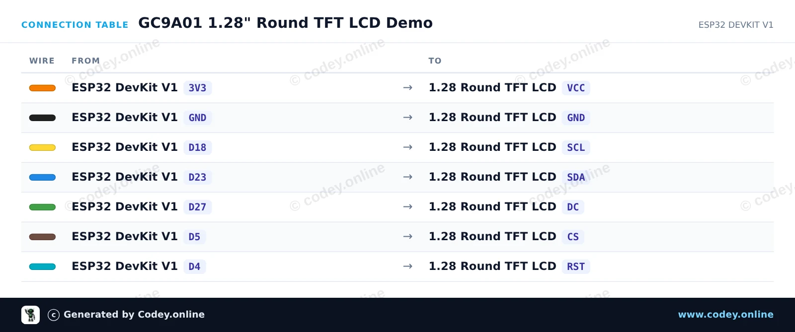
This project connects a 1.28-inch GC9A01 round TFT LCD to the ESP32 via SPI. The sketch initializes the display and draws a custom round gauge layout with text and updating status indicators.

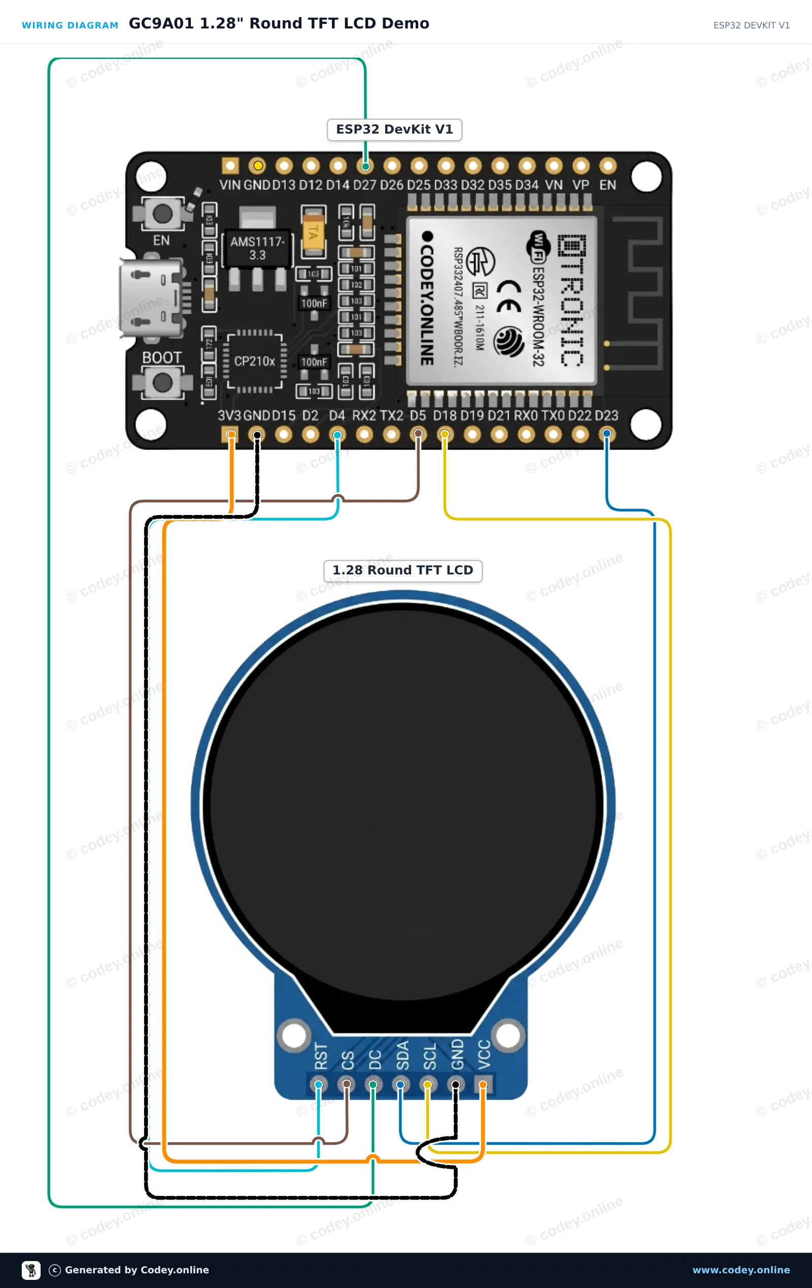
Wiring diagram: 1.28″ round TFT LCD 240×240 (GC9A01, SPI) for Arduino on an ESP32 DevKit V1
Wiring diagram · Click to enlarge
Connection table: 1.28″ round TFT LCD 240×240 (GC9A01, SPI) for Arduino on an ESP32 DevKit V1
Connection table · Click to enlarge
GC9A01_1_28_Round_TFT_LCD_Demo.ino · compiled and verified
/*
 * ==================================================================
 *  Generated by Codey.online  —  https://www.codey.online
 * ==================================================================
 *  Project   : GC9A01 1.28" Round TFT LCD Demo
 *  Board     : ESP32 DEVKIT V1 (esp32:esp32:esp32doit-devkit-v1)
 *  Parts     : 1.28" Round TFT LCD 240x240 (GC9A01, SPI)
 *  Libraries : Adafruit GFX Library 1.12.6, Adafruit GC9A01A 1.1.1
 *
 *  Codey Online is an AI-powered browser IDE for Arduino and ESP32.
 *  Describe your project and Codey writes the code, draws the wiring
 *  diagram and uploads it to your board, straight from the browser.
 *  This code is free to use, modify and share, without warranty.
 * ==================================================================
 */

#include <SPI.h>
#include <Adafruit_GFX.h>
#include <Adafruit_GC9A01A.h>

#define TFT_CS   5
#define TFT_DC   27
#define TFT_RST  4

Adafruit_GC9A01A tft(TFT_CS, TFT_DC, TFT_RST);

void drawDial() {
  tft.fillScreen(GC9A01A_BLACK);
  
  // Draw outer colored rings
  tft.drawCircle(120, 120, 118, GC9A01A_CYAN);
  tft.drawCircle(120, 120, 115, GC9A01A_BLUE);
  tft.fillCircle(120, 120, 90, GC9A01A_NAVY);
  tft.fillCircle(120, 120, 80, GC9A01A_BLACK);

  // Centered labels
  tft.setTextColor(GC9A01A_WHITE);
  tft.setTextSize(2);
  tft.setCursor(65, 80);
  tft.println("GC9A01");

  tft.setTextSize(1);
  tft.setTextColor(GC9A01A_GREEN);
  tft.setCursor(75, 105);
  tft.println("ESP32 READY");
}

void setup() {
  Serial.begin(115200);
  Serial.println("Initializing GC9A01 Round Display...");

  tft.begin();
  tft.setRotation(0);
  drawDial();
  Serial.println("Display initialized!");
}

void loop() {
  static unsigned long lastUpdate = 0;
  static int counter = 0;

  if (millis() - lastUpdate >= 1000) {
    lastUpdate = millis();
    counter++;

    // Update counter display in the center
    tft.fillRect(60, 130, 120, 30, GC9A01A_BLACK);
    tft.setTextColor(GC9A01A_YELLOW);
    tft.setTextSize(3);
    tft.setCursor(95, 135);
    tft.printf("%02d", counter % 60);

    Serial.print("Counter: ");
    Serial.println(counter % 60);
  }
}

Required libraries: Adafruit GFX Library 1.12.6, Adafruit GC9A01A 1.1.1

Wiring diagram and example code generated by Codey.online — https://www.codey.online

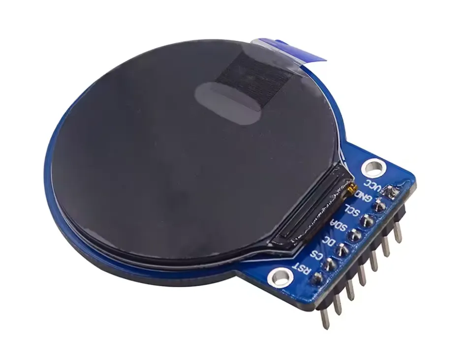
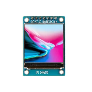
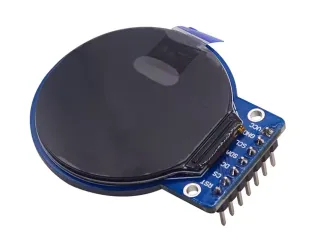
1.28″ round TFT LCD 240×240 (GC9A01, SPI) for Arduino

This 1.28 inch round TFT LCD display is ideal for Arduino projects that require a bright and sharp screen. With a resolution of 240×240 pixels and an IPS color display, it offers a fully visible and vivid display from any angle.

Main features

  • Screen size: 1.28 inch round
  • Resolution: 240×240 pixels
  • Display type: IPS color display for wide viewing angles
  • Driver chip: GC9A01
  • Interface: 4-Pin SPI
  • Operating voltage: 2.8V to 3.3V
  • Pin pitch: 2.54 mm, 8 pins
  • Operating temperature: -20℃ to 70℃
  • Operating humidity: 5% to 95% RH

Technical specifications

  • Display area: 32.4 mm diameter
  • Panel dimensions: 35.6 × 38.1 × 1.5 mm
  • PCB dimensions: 44 × 36 × 5 mm
  • Fully visible angle for optimal readability

This display is suitable for various applications where a compact, high-quality color display is needed. Thanks to the SPI interface, it is easy to connect to Arduino and similar microcontrollers.

  • 1.28-inch round
  • 240×240 pixels
  • GC9A01 driver
  • 4-Pin SPI

Why choose this product?

  • Clear image – IPS color display with sharp rendering.
  • Wide viewing angles – Fully visible from any angle.
  • Easy to connect – Suitable for Arduino via SPI.
  • Compact display – For applications with a small color screen.
Specifications
Pin spacing2.54 mm, 8 pins
Screen size1.28 inch round
Resolution240×240 pixels
Display typeIPS color display for wide viewing angles
Driver chipGC9A01
Interface4-Pin SPI
Operating voltage2.8V to 3.3V
Operating temperature-20℃ to 70℃
Operating humidity5% to 95% RH
Display area32.4 mm diameter
Panel dimensions35.6 × 38.1 × 1.5 mm
PCB dimensions44 × 36 × 5 mm

Frequently bought together

Total: € 16,03

Reviews

★★★★★ 5,0/5 1 review
  • ★★★★★roan thieleVerified purchase

    Very nice display, difficult to code properly

Write a review
Your rating

Shipping & returns

Shipping

  • Parcel with track & trace€ 7,70Within 24 hours
  • Pick up at PostNL location€ 7,40Within 24 hours
  • Letterbox parcel€ 3,70Within 2 business days
  • Letterbox parcel 24 hours€ 4,55Within 24 hours
  • Pick up in storeFree
All about shipping

Returns

Not satisfied? You have 30 days after delivery to return the product.

All about returns

Recently viewed