






 Nederlands
 Suomi
 Български
 Hrvatski
 Frans
 Deutsch
 Italiano
 Español
 Polski
 Dansk
 Ελληνικά
 Čeština
 Svenska
 Aileen
Line-Following Robot Kit (OT9082) – Instruction Manual
This instruction manual explains how to assemble the OT9082 Line-Following Robot Kit yourself by soldering it together. Required tools: soldering iron, solder wire and side cutters.
Component list
| Component | Location | Component | Location |
|---|---|---|---|
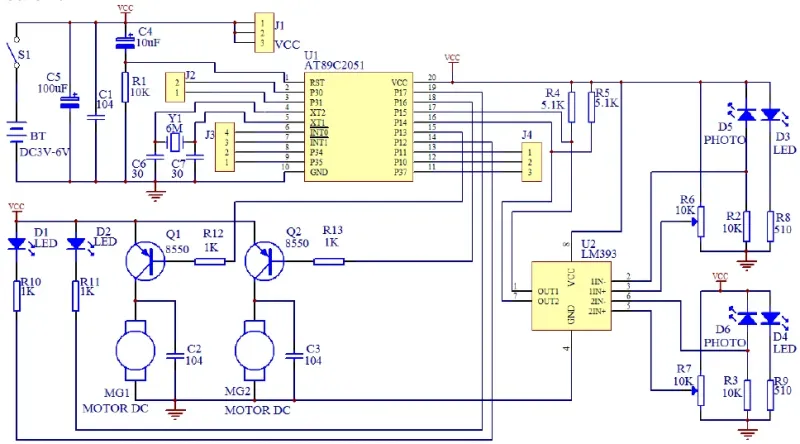
| Resistor 510Ω | R8, R9 | Green LED 3mm | D1, D2 |
| Resistor 1KΩ | R10, R11, R12, R13 | Infrared LED transparent | D3, D4 |
| Resistor 5.1KΩ | R4, R5 | Infrared LED black | D5, D6 |
| Resistor 10KΩ | R1, R2, R3 | Transistor 8550 | Q1, Q2 |
| Capacitor 10 µF | C4 | Potentiometer 10KΩ | R6, R7 |
| Capacitor 100 µF | C5 | 24-pin IC socket | U1 |
| Crystal 6Mhz | Y1 | 8-pin IC socket | U2 |
| Ceramic capacitor 30 | C6, C7 | On/off switch | S1 |
| Ceramic capacitor 104 | C1, C2, C3 |
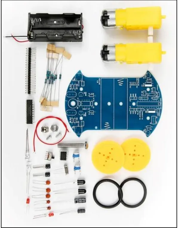
Package contents
- 3x Ceramic capacitor (104)
- 2x Ceramic capacitor (30)
- 1x Capacitor (10µF)
- 1x Capacitor (100µF)
- 1x 20-pin header
- 1x Crystal (6 Mhz)
- 2x Green LED (3mm)
- 2x Infrared LED (5mm)
- 2x Infrared receiver LED (5mm)
- 2x Transistor (8550)
- 3x resistor (10KΩ)
- 2x resistor (510Ω)
- 4x resistor (1KΩ)
- 2x resistor (5.1KΩ)
- 2x resistor (10KΩ)
- 1x IC Atmel 89C2051 24-pin
- 1x IC socket 24-pin
- 1x IC LM393 8-pin
- 1x IC socket 8-pin
- 2x TT motor JD3-100
- 2x Plastic wheel
- 2x Silicone bands
- 2x wheel screw
- 1x battery holder (2x AA)
- 1x PCB
- 1x support screw with nut and cap nut
- 1x black wire
- 1x red wire
- 1x On/off switch
- 2x double-sided tape for motor mounting
Assembly instructions
The polarity of the infrared LED transmitter and receiver is reversed.
The ICs and socket must be placed in the correct direction. The components and their locations are listed on the back side.
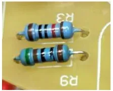 Start by soldering the resistors. Resistors are not polarized, which means you can place them in either direction and there is no + or –.
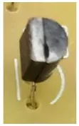 Solder the transistors and make sure that the flat side and the round side match the image on the PCB.
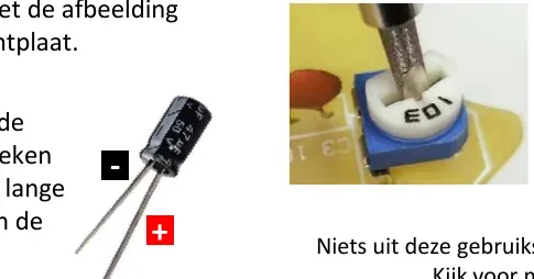
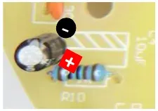 Solder the capacitors and pay close attention to the + and the -. The capacitor has a white band shown with a minus sign in it. You can also tell by the length of the leads. The long lead is the + and the short lead is the -. On the PCB, the slanted white stripes indicate the - side.
 Solder the ceramic capacitors. These are not polarized, so it does not matter how they are placed (no + or – side).
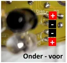 Solder the green 3mm LEDs and the infrared receiver and transmitter LEDs. On each LED, the long lead is the + and the short lead is the -. The minus side can also be identified by the flat side on the LED itself. The polarity of the transmitter LED is opposite to that of the receiver LED. Pay attention to the lead lengths.
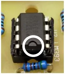 Solder the IC sockets in place. Pay attention to the half-round notch. This must match the image on the PCB. Then place the ICs in the socket, and the ICs also have a half-round notch that must face the same side as the socket.
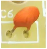 Solder the ceramic capacitors in place (alternative image). These are not polarized.
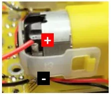 Solder the supplied wiring to the DC motors and to the PCB. Pay attention to the polarity. When the wheels rotate, they must always turn forward. On the PCB, the + is mounted on the outside and the – on the inside.
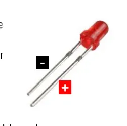 Solder the ceramic capacitors in place with the red wire connected.
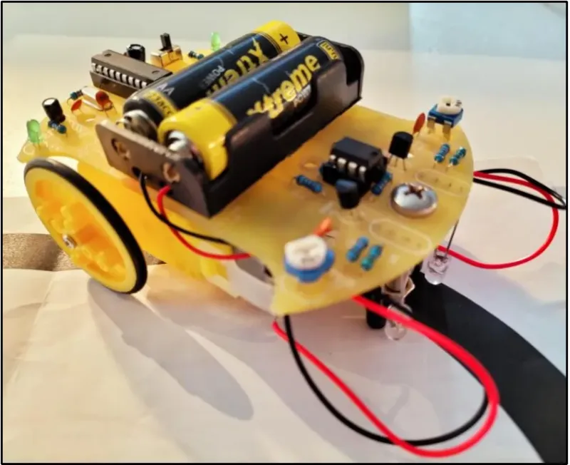
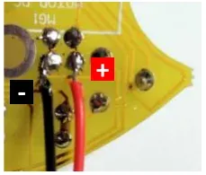 Solder the remaining components such as the potentiometers and the on/off switch in the correct location. Mount the wheels on the motor shafts and then stick the motors to the PCB using the double-sided tape.
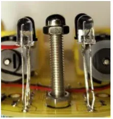 Mount the screw with the cap nut on the underside of the PCB. Make sure the infrared LEDs are just slightly shorter than the screw head. The robot rests on this round cap nut. Ideally, the distance between the infrared LEDs and the ground is 1 a 2mm.
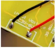 Mount the battery holder and solder the wires to the PCB.
- Calibrate the sensitivity of the infrared sensors by turning the potentiometers.
OTRONIC® is a registered trademark. Nothing from this instruction manual may be copied without permission from OTRONIC. For more information about OTRONIC products, visit OTRONIC.NL. OTRONIC – Crommelinbaan 61c – 2142 EX – Cruquius – Nederland.